Differential common collector amplifying circuit

A common collector and amplifying circuit technology, which is applied in the field of amplifying signal current devices, can solve problems such as poor anti-common-mode interference performance, high signal-to-noise ratio, and large distortion, and achieve high power utilization and anti-common-mode interference capabilities Strong, low distortion effect

Inactive Publication Date: 2008-07-30
黄骐
View PDF0 Cites 6 Cited by
  • Summary
  • Abstract
  • Description
  • Claims
  • Application Information

AI Technical Summary

Problems solved by technology

[0003] In order to overcome the disadvantages of poor anti-common-mode interference performance and large distortion of existing current amplifying circuits, the patent of the present invention provides a differential common-collector amplifying circuit, which can effectively resist common-mode interference, with high signal-to-noise ratio and low distortion

Method used


Image

  • Differential common collector amplifying circuit
  • Differential common collector amplifying circuit
  • Differential common collector amplifying circuit

Examples


Embodiment Construction

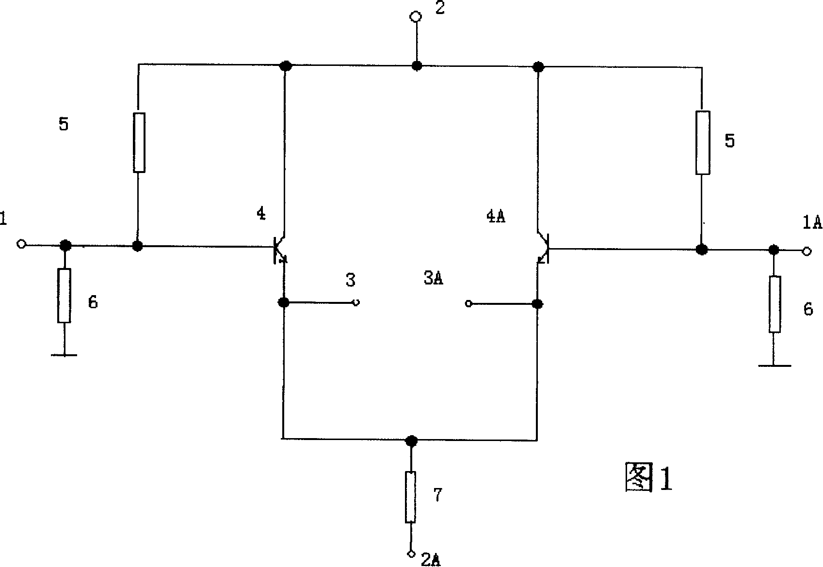
[0012] In Figure 1, the signal is balanced by the signal balanced input terminal (1.(1A.)). Balanced output from the signal balance output terminal (3.(3A.)). The circuit is respectively connected to the positive and negative sides of the power supply through the positive potential terminal (2.) and the negative potential terminal (2A.) of the power supply to supply power to the circuit. The two transistors (4. (4A.)) are: the same model and the same specification. The transistor is statically biased by the bias resistor (5.) on the transistor, so that the static operating point of the transistor can be selected by adjusting its resistance value. The balance of the positive and negative half cycle amplitudes of the signal input is realized by the grounding resistance (6.) of the signal terminal. The common mode signal negative feedback of the circuit is provided by the common emitter resistor (7) of the transistor. The input can be either balanced or single-ended. For sing...


PUM


Abstract

The invention relates to a difference common collector amplifying circuit which is a device of an amplifying signal current for decreasing the distortion factor of a power amplification circuit. At present, a well-known current amplifying circuit of a station amplifier generally adopts an OCL circuit, in which the utility ratio of a power supply is higher, the direct coupling is realized, the circuit is simple and the power is big, but the performance of common-mode interference resistance of the circuit is reduced because non-equilibrium design is adopted, and the distortion is larger. Based on a traditional monotube common collector amplifying circuit, the difference common collector amplifying circuit introduces a difference structure, and a fully symmetrical and balanceable circuit structure is used for resisting the common-mode interference. The invention can be mainly used in the fields of low-frequency signal current amplification, aural signal current amplification, amplifier impedance match, an amplifier high input impedance input circuit, an amplifier low input impedance output circuit, single end-balanced signal transformation, etc.

Description

Technical field [0001] The patent of the present invention relates to a device for amplifying signal current, especially capable of reducing the distortion degree of a power amplifying circuit. Background technique [0002] Currently, known power amplifier current amplifying circuits generally use OCL circuits. High power utilization allows for direct coupling. The circuit is simple and the power is large. However, its unbalanced design degrades the performance of the circuit against common-mode interference, resulting in large distortion. Contents of the invention [0003] In order to overcome the disadvantages of poor anti-common-mode interference performance and large distortion of existing current amplifying circuits, the patent of the present invention provides a differential common-collector amplifying circuit, which can effectively resist common-mode interference, with high signal-to-noise ratio and low distortion . [0004] The technical scheme adopted by the i...

Claims


Application Information

Patent Timeline
Patent Type & Authority Applications(China)
IPC IPC(8): H03F1/32H03F3/20H03F3/45
Inventor 黄骐
Owner 黄骐
Why Eureka
Try Eureka