Dual antenna

A dual-antenna and antenna technology, applied in antennas, electrical short antennas, antenna components, etc., can solve the problems of increasing manufacturing costs and unreachable, and achieve the effects of improving overall matching, good isolation, and good antenna efficiency

Inactive Publication Date: 2008-08-06
PULSE FINLAND
View PDF0 Cites 10 Cited by
  • Summary
  • Abstract
  • Description
  • Claims
  • Application Information

AI Technical Summary

Problems solved by technology

[0012] The drawback of the above dual antenna solution is that the matching of the antennas in both the lower and upper operating frequency bands needs to be arranged, which increases the manufacturing cost and still does not achieve the desired result

Method used


Image

  • Dual antenna
  • Dual antenna
  • Dual antenna

Examples


Embodiment Construction

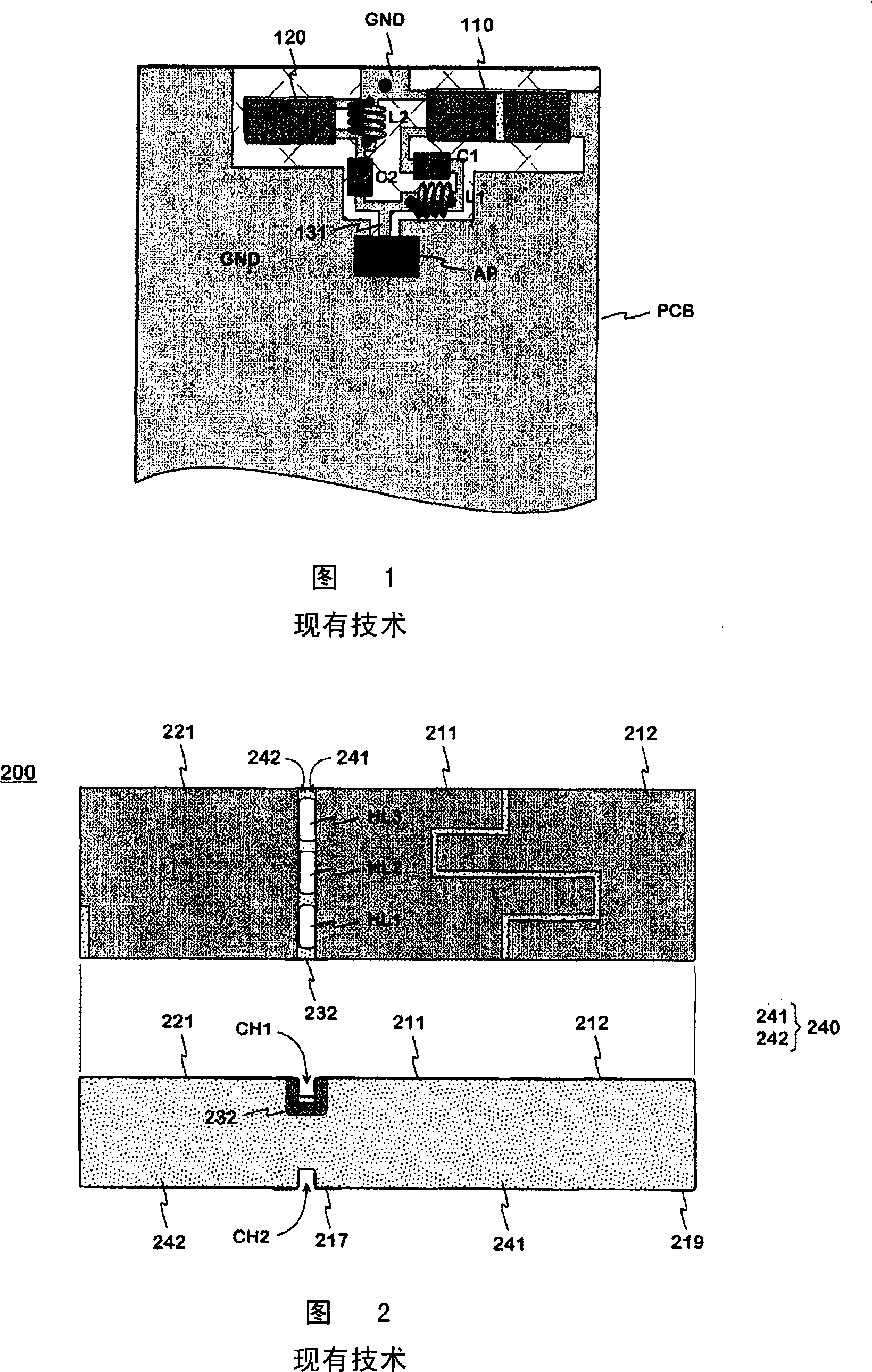
[0029] Figures 1 and 2 have already been described in the introduction relating to the prior art.

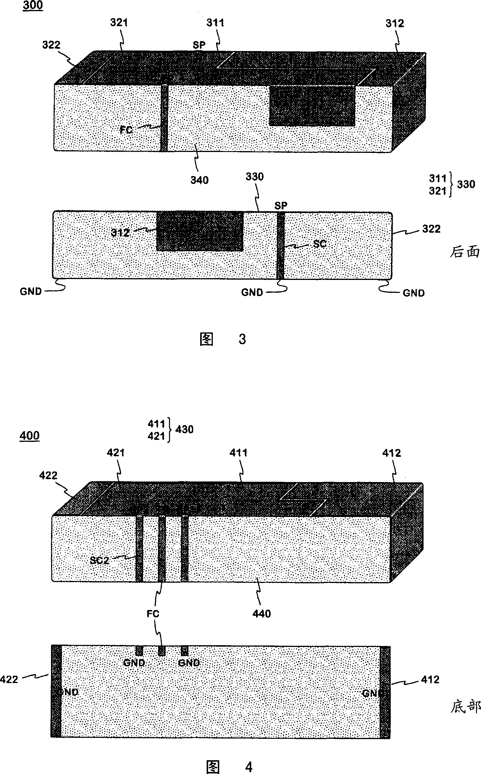
[0030] Fig. 3 shows an example of a dielectric dual antenna according to the invention. It has a first partial antenna and a second partial antenna, the lower operating frequency band of the entire antenna is realized by the first partial antenna, and the higher operating frequency band is realized by the first partial antenna. In this figure, the antenna assembly 300 is a perspective view from the front, and in the second part of the drawings from the rear. The antenna also belongs functionally to the ground plane on the printed circuit board of the radio device, on which the antenna components are mounted. The integrated antenna component 300 comprises a substrate 340 shared between the partial antennas, and an antenna radiating element as a conductor cladding of the substrate. Substrate 340 is here an elongated ceramic sheet substantially shaped like a rectangular prism wit...


PUM


Abstract

A dielectric dual antenna intended especially for small-sized radio devices, by one partial antenna of which is implemented the lower operating band of the antenna and by the other partial antenna the upper operating band. The partial antennas have a shared substrate (440), which together with the radiators constitutes an integrated antenna component (400). The partial antennas also have a shared feed point (FP), the part of the antenna component to one direction from the plane, which leads through the feed point and is perpendicular to the upper surface of the substrate, belonging to one partial antenna and the part of the antenna component to the opposite direction belonging to the other partial antenna. At least one of the partial antennas comprises two radiators, the first one (411) of which joins the feed point and the second one (412) is connected to the ground (GND) from its outer end as viewed from the first radiator. This first radiator (411) and the radiator (421) of the other partial antenna, which joins the shared feed point, form a unitary common element (430) on the substrate surface. This common element is shortcircuited to the ground from at least one point (SP1, SP2) relatively near to the feed point. The matching of the dual antenna can be improved in either operating band without degrading it in the other operating band at the same time.

Description

technical field [0001] The present invention relates to an antenna structure for a small radio device comprising two electrically oppositely separated parts to realize two operating frequency bands. Background technique [0002] In small portable radio devices such as mobile phones, it is preferable to place the antenna within the housing of the device for ease of use. Furthermore, the design of the antenna is demanding as it tries to occupy as little space as possible. Additional design difficulties arise if the radio has to operate in several frequency ranges, the more difficult the wider these frequency ranges are. [0003] Internal antennas are mostly planar structures, in which case they comprise a radiating surface and a ground plane at a certain distance from the radiating surface. Planar antennas can be made smaller by making the radiating surface on the surface of a dielectric substrate instead of insulating it from air. The higher the dielectric constant of a ma...

Claims


Application Information

Patent Timeline
Patent Type & Authority Applications(China)
IPC IPC(8): H01Q1/38H01Q5/00H01Q21/30H01Q5/10H01Q5/371
CPCH01Q5/00H01Q5/371H01Q1/38H01Q9/0442H01Q5/0058H01Q1/243H01Q9/00H01Q9/0421
Inventor P·尼西南
Owner PULSE FINLAND
Why Eureka
Try Eureka