Scanning method and apparatus

A technology of scanning system and field of view, which is applied in the field of scanning and equipment, can solve the problem of location connection and other problems, and achieve the effect of meeting real-time requirements

Inactive Publication Date: 2008-08-06
THRUVISION LTD
View PDF2 Cites 12 Cited by
  • Summary
  • Abstract
  • Description
  • Claims
  • Application Information

AI Technical Summary

Problems solved by technology

[0013] Embodiments of the present invention can solve the problem of relating detector output to position in the field of view by utilizing an electromagnetic tracking beam to directly track the movement of a moving part

Method used


Image

  • Scanning method and apparatus
  • Scanning method and apparatus
  • Scanning method and apparatus

Examples


Embodiment Construction

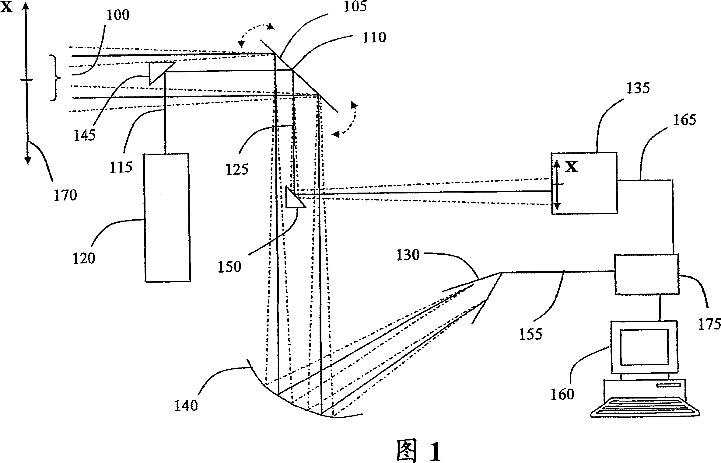
[0051] It should be noted that none of the figures described are drawn to scale. All drawings are schematic only. Where the same parts are shown in different drawings, the same reference numerals are used.

[0052] Referring to FIG. 1 , the main parts of the terahertz imaging system that can be used in embodiments of the present invention include: a scanning device 105, such as a mirror that can be used in an optical imaging system; 100 is focused on a horn antenna 130 . (The input terahertz radiation 100 is collimated in a known manner using corrective optics not shown in the figures.) Horn antenna 130 is a known type of antenna and converts the terahertz radiation into a An intensity-modulated electrical output signal on the input terahertz radiation 100 . Furthermore, the focusing device 140 may also be a component that may be used in an optical system, such as a concave mirror as shown.

[0053] Horns and planar antennas are well-known directional components used to co...


PUM


Abstract

In a terahertz imaging system, a light beam (115) tracks a scanning component (105) for scanning a field of view in order to obtain positional information. The tracking beam (115) may be steered by the scanning component (105), for example, by means of reflection, refraction or diffraction. The steered tracking beam (125) can then be detected by a spatially sensitive detector such as a charge-coupled device array (135). In a preferred embodiment, the output of a terahertz detector (130) receiving terahertz radiation from a scanned field of view (170) is used to modulate the tracking beam (115). This means that the spatially sensitive detector (135) can provide an image directly derived from the scanning of the field of view by terahertz radiation.

Description

technical field [0001] The present invention relates to scanning methods and apparatus for imaging objects using the electromagnetic spectrum with wavelengths in the millimeter to submillimeter range, and in particular, but not exclusively, to heterodyne detector based configurations. Background technique [0002] The aforementioned range is generally referred to herein as the terahertz spectrum. Terahertz radiation has been found to be a useful tool for imaging and other purposes because certain materials that are opaque to the visible spectrum are transparent to terahertz radiation. This allows the use of terahertz radiation to "see through" these materials where visible radiation cannot be used. For example, terahertz wavelengths have been used to image the Earth's surface through the atmosphere and to improve visibility in bad weather (eg, for flying or driving). Certain materials can be distinguished under terahertz radiation conditions due to their unique transmittan...

Claims


Application Information

Patent Timeline
Patent Type & Authority Applications(China)
IPC IPC(8): G01V8/00
CPCG01V8/005
Inventor C·M·曼D·J·库姆斯M·费尔莱特
Owner THRUVISION LTD
Why Eureka
Try Eureka