Perspective latent image of anopisthographic printing

A latent image, single-sided technology, applied in the field of anti-counterfeiting, can solve the problems of difficulty in see-through latent image, unidentifiable patterns, high precision, etc., and achieve the effects of strong anti-counterfeiting performance, improved aesthetics, and high metallic luster

Active Publication Date: 2008-08-13
CHINA BANKNOTE PRINTING & MINTING
View PDF0 Cites 3 Cited by
  • Summary
  • Abstract
  • Description
  • Claims
  • Application Information

AI Technical Summary

Problems solved by technology

This kind of latent image cannot be recognized as a complete pattern when viewed under normal light on one side, and the pattern needs to be separated during design. A special gravure printing machine is required for printing, and the printing overprinting accuracy is high to achieve perspective Hiding is more difficult

Method used


Image

  • Perspective latent image of anopisthographic printing

Examples


Embodiment 1

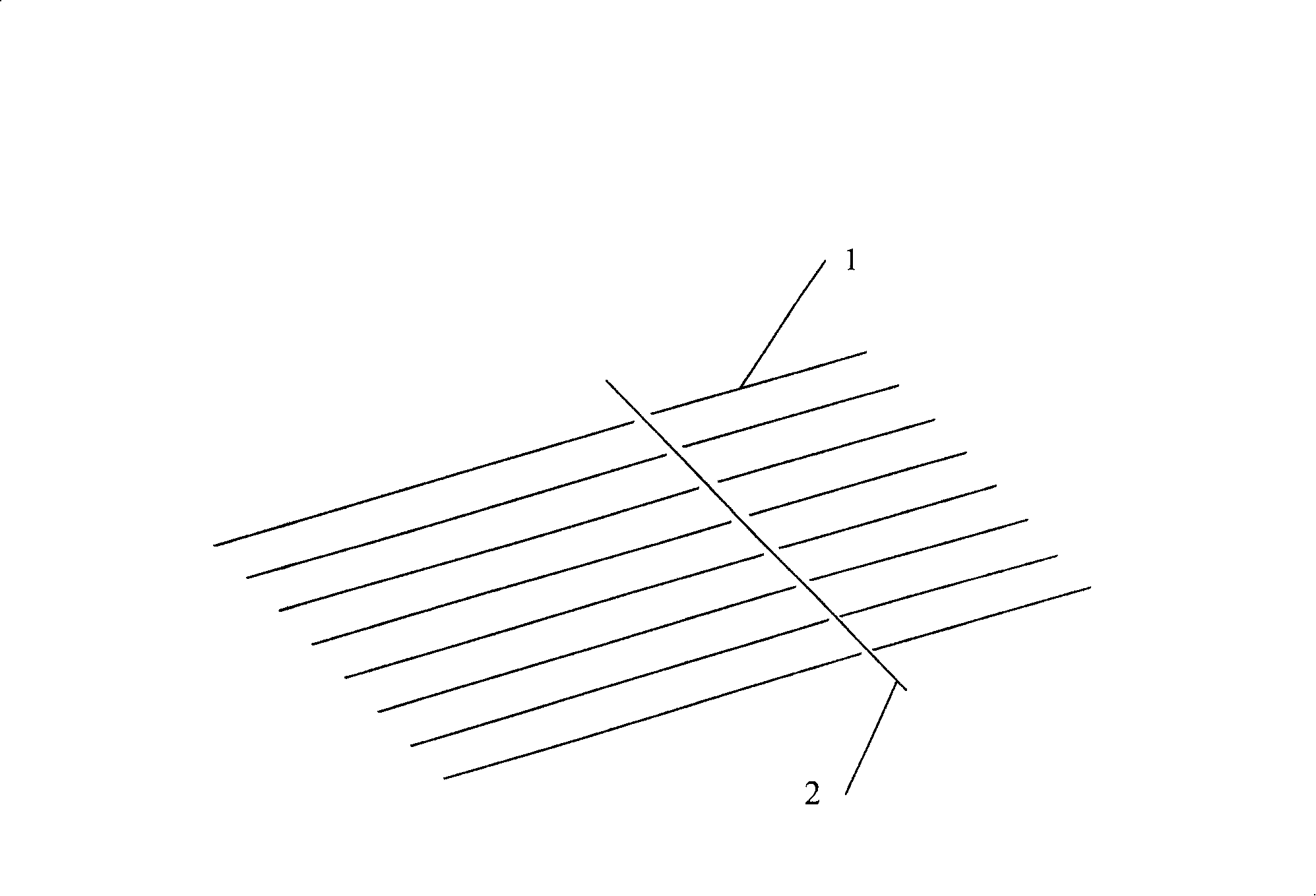
[0033] Embodiment 1: Utilize the software of engraving gravure design to generate the base pattern and the perspective latent image pattern made of lines, the lines constituting the perspective latent image pattern and the lines forming the pattern are as follows figure 1 In the arrangement shown, the two intersect at an angle of 90° but do not overlap each other, and the density of the lines forming the perspective latent image pattern is 5 lines per millimeter. Then through the existing engraving gravure printing process, the see-through latent image pattern and the base pattern are printed on one side of the carrier (or referred to as the substrate) at one time with metallic ink. The carrier can be paper, such as banknote paper, security paper , license paper or bill paper, or plastic, rubber, glass and other items with a certain degree of light transmission.

[0034] The composition and weight percentage of the metal ink used to form the see-through latent image are as fol...

Embodiment 2

[0048] Embodiment 2: The basic structure and implementation method are as in embodiment 1, wherein the density of lines constituting the see-through latent image pattern is 6 per millimeter, and is used for printing the metal ink of the lines of the see-through latent image and the base pattern on one side on the carrier The ingredients and percentages are as follows:

[0049] Flake aluminum powder 20%

[0050] Alkyd Oil 15%

[0051] High acid value phenolic resin oil 20%

[0052] Pure Phenolic Oil 10%

[0053] Fumed silica 5%

[0054] Transparent Calcium Carbonate 15%

[0055] Surfactant 6.7%

[0056] Polyethylene wax 6%

[0057] Mineral oil 2%

[0058] Desiccant 0.3%

Embodiment 3

[0059] Embodiment 3: The basic structure and implementation method are as in Embodiment 1, wherein the density of lines constituting the see-through latent image pattern is 7 per millimeter, and is used for printing the metal ink of the lines of the see-through latent image and the base pattern on one side on the carrier The ingredients and percentages are as follows:

[0060] Flake copper powder 24%

[0061] Alkyd Oil 10%

[0062] High acid value phenolic resin oil 24%

[0063] Pure Phenolic Oil 8%

[0064] Fumed silica 3%

[0065] Transparent Calcium Carbonate 16%

[0066] Surfactant 5.6%

[0067] Polyethylene wax 6%

[0068] Mineral oil 3%

[0069] Desiccant 0.4%


PUM

PropertyMeasurementUnit
viscosityaaaaaaaaaa

Abstract

The invention discloses a single-side printed perspective latent image and relates to an anti-fake technology, whose aim is to provide a perspective latent image which is single-side printed, needn't get help from a particular instrument, is easy to be distinguished by public, has a stronger anti-fake function, and is easier to be realized. The latent image comprises metal printing ink which adheres on a side of a photic carrier. The metal printing ink prints via an engraving gravure and adheres with the carrier. The perspective latent image is implicated in a base pattern on the carrier, and metal printing ink streaks forming the perspective latent image intersect but not overlapped intersect to form a 90 degrees angle with the metal printing ink streaks forming the base pattern. The thickness of the metal printing ink streaks forming the perspective latent image is 5 metal printing ink streaks to 8 metal printing ink streaks in each millimeter. A pattern forming the perspective latent image and the base pattern are unified designed and printed simultaneously in one time to adhere with the carrier via the engraving gravure printing mode. The method can be applied to various portfolios such as paper money, securities, licenses, bills and so on, also can be applied to the carriers such as plastics, rubber, glass and so on which is provided with a certain light transmittance.

Description

technical field [0001] The invention relates to an anti-counterfeiting technology, in particular to a see-through latent image with anti-counterfeiting effect printed on one side on a light-permeable carrier. Background technique [0002] Latent image is an anti-counterfeiting technology that hides specific patterns at normal viewing angles and observes and recognizes them under specific observation conditions. It is a technology widely used in the field of anti-counterfeiting printing. It has concealed anti-counterfeiting and easy identification. features. [0003] At present, the most widely used latent image technology is to use colorless fluorescent ink printing, and the printed pattern is hidden under visible light and clearly visible under ultraviolet light. But this kind of latent image requires the help of a specific instrument (ultraviolet light source), and the technical threshold for counterfeiting is relatively low, which has been broken by counterfeiters, and t...

Claims


Application Information

Patent Timeline
Patent Type & Authority Applications(China)
IPC IPC(8): B44F1/00B44F1/06B41M3/10C09D11/02C09D11/50
Inventor 李军黄小义房晓龙潘东王自森邱燕新张勇詹刚
Owner CHINA BANKNOTE PRINTING & MINTING
Why Eureka
Try Eureka