Cylinder type hologram manufacture method, manufacture device and manufactured hologram

A manufacturing method and a technology for manufacturing devices, which are applied in the field of holography, can solve the problems of limited application range, waste of laser energy, difficulty in control, etc., and achieve the effects of cost reduction and wide range

Inactive Publication Date: 2008-08-13
AFC TECH
View PDF0 Cites 9 Cited by
  • Summary
  • Abstract
  • Description
  • Claims
  • Application Information

AI Technical Summary

Problems solved by technology

Therefore, for a recording system with a fixed radius of curvature, only cylindrical holograms with the same radius can be produced. That is to say, for cylinders with different radii, a corresponding cylindrical lens 61 is required. This greatly limits the scope of application of the method
In addition, due to the complexity of this recording optical system, after the laser passes through the optical system, the energy of the laser is wasted a lot, and the laser energy falling on the holographic recording material is reduced; The laser distribution is relatively scattered and not concentrated enough, which not only requires high laser power, but also can be better realized only on expensive and high-sensitivity holographic recording materials, such as the oldest and commonly used recording medium-silver salt, Its photosensitive sensitivity is very high, but it is difficult to control, the cost is high, and it is not easy to mass produce, which makes it difficult for the traditional cylindrical hologram to be widely used
It is very difficult to realize on low photosensitivity materials such as photoresist (such as photoresist plate, whose photosensitivity is two orders of magnitude lower than that of silver salt), so no holographic products with similar effects have been seen so far.

Method used


Image

  • Cylinder type hologram manufacture method, manufacture device and manufactured hologram
  • Cylinder type hologram manufacture method, manufacture device and manufactured hologram
  • Cylinder type hologram manufacture method, manufacture device and manufactured hologram

Examples


Embodiment Construction

[0040] The present invention will be further described below in conjunction with the accompanying drawings and preferred embodiments.

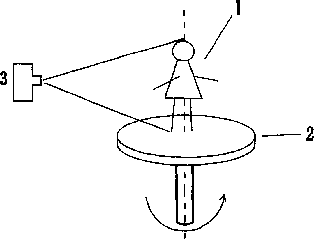
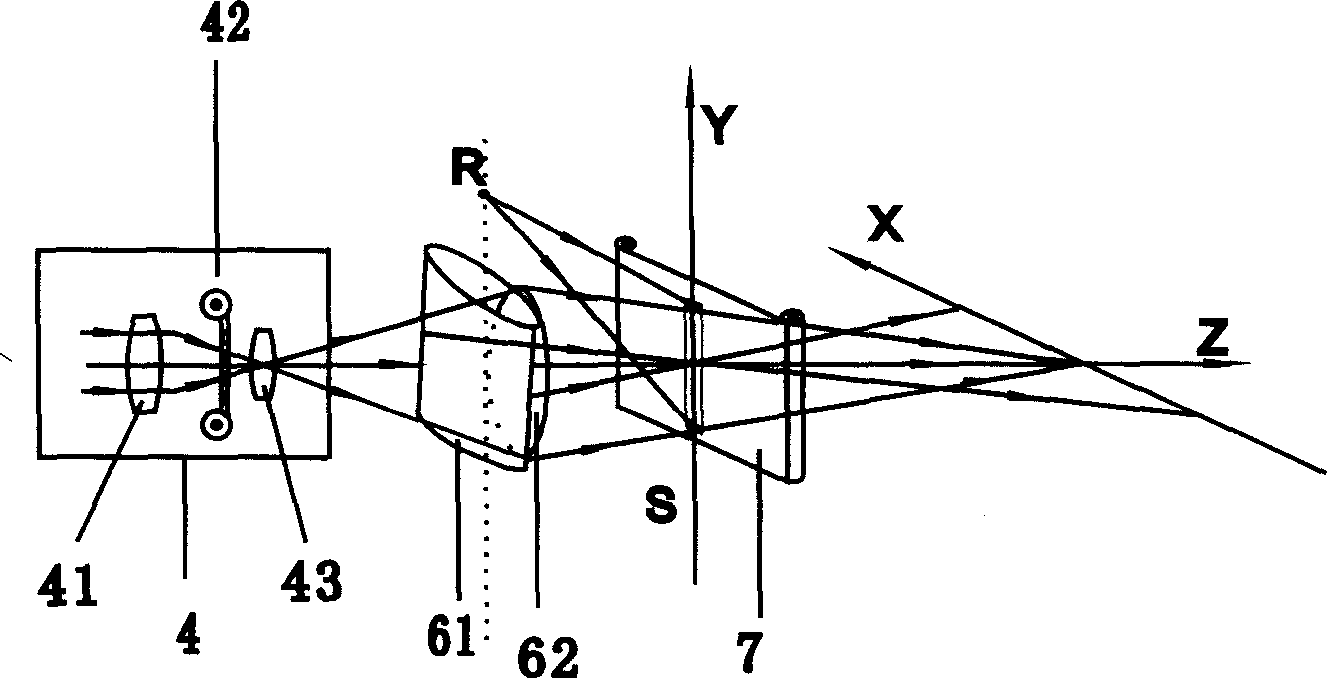
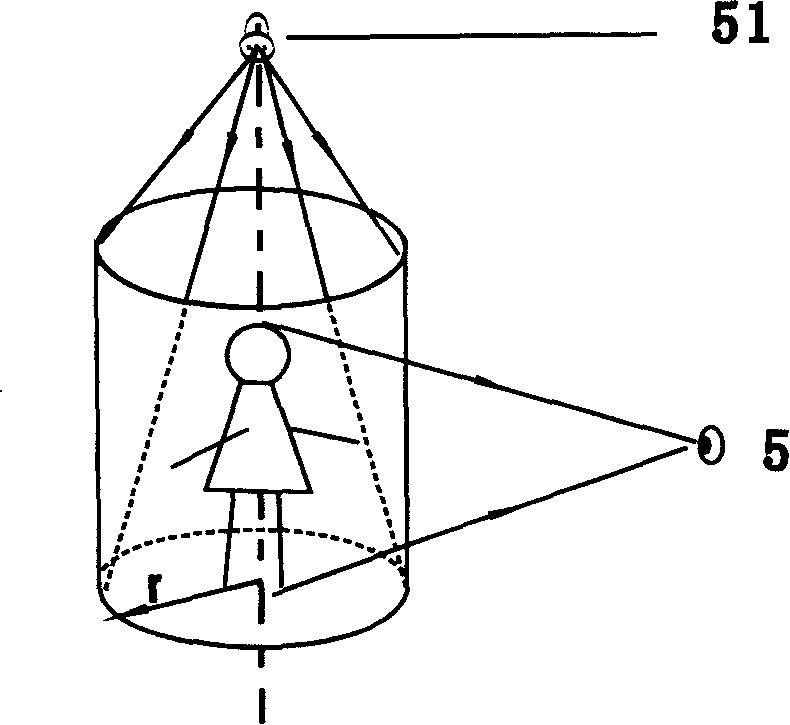
[0041] The production principle of the traditional cylindrical hologram is as follows: After collecting N images of different viewing angles (take the 360° viewing angle as an example, such as figure 1 shown), the nth pattern is projected onto the cylindrical lens 61 and the field lens 62, and the pattern is compressed to the vicinity of the hologram by the cylindrical lens 61 to form a narrow strip-shaped unit hologram for recording, and N All images are compressed onto the holographic recording material 7 to form a cylindrical hologram. Therefore, the radius r of the finally formed cylindrical hologram is equal to the distance from the holographic recording material 7 to the cylindrical lens 61 and depends on the radius of curvature of the cylindrical lens 61 . Fig. 4 shows the imaging process of each unit hologram during the reproduction p...


PUM


Abstract

The invention discloses a making method for a cylindrical hologram, a making device and a made hologram thereby. The making method comprises following steps: encoding each line information after dividing a plurality of digital images with different visual angles into a plurality of line information; reading the encoded line information by a projection system, condensing the read line information by laser permeating the projection system at a corresponding point of the holographic recording material; recording each line information of each gram spot by spot until a unit hologram is recorded; recording each unit hologram row by row until unit holograms of all view angles are all recorded on the corresponding holographic recording material. The invented method divides and encodes an image into a plurality of line information, records the line information spot by spot on the holographic recording material disposed on the focus of the imaging lens, and the line information is packed recorded by an imaging lens, so that the radius of the final cylindrical hologram is adjusted by adjusting the object distance.

Description

technical field [0001] The present invention relates to the technical field of hologram, and more specifically, relates to a method for making a cylindrical hologram, a making device and the prepared hologram. Background technique [0002] Since its invention, holography has been an ideal tool for people to support their dreams of three-dimensional display. The breakthrough of recording materials, the birth of digital holography, and the emergence of various low-cost and high-quality laser light sources indicate that people's dreams and efforts for nearly half a century are rapidly becoming reality. Display holography is gradually entering people's daily life from the palace of science and art, challenging people's basic understanding of existing information technology to the greatest extent. The object of future information technology is not just ordinary two-dimensional plane information processing, but the collection, encoding, transmission, demodulation and display of i...

Claims


Application Information

Patent Timeline
Patent Type & Authority Applications(China)
IPC IPC(8): G02B5/32G03H1/04G03H1/22
Inventor 范诚蔡志森柯重来陈曼东卢玮
Owner AFC TECH
Why Eureka
Try Eureka