Supercharge Your Innovation With Domain-Expert AI Agents!

Photo mask pattern correction method

A correction method and photomask technology, applied to the photolithographic process of the pattern surface, the original for photomechanical processing, optics, etc., can solve the problems of not being able to obtain results similar to the original pattern, wasting time for correcting actions, etc.

Inactive Publication Date: 2008-08-13
UNITED MICROELECTRONICS CORP
View PDF0 Cites 7 Cited by
  • Summary
  • Abstract
  • Description
  • Claims
  • Application Information

AI Technical Summary

Problems solved by technology

Therefore, when the layout pattern presents an asymmetric layout, if the analog optical proximity correction method is used in the isolated pattern area, it will waste time to correct the action, and if the reference optical proximity correction method is used, the dense pattern area will not be obtained. Similar results to the original pattern

Method used


Image

  • Photo mask pattern correction method
  • Photo mask pattern correction method
  • Photo mask pattern correction method

Examples


Embodiment Construction

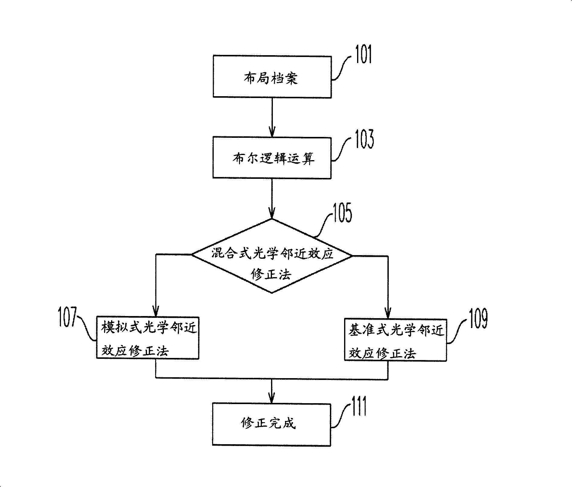
[0044] As the size of the components is getting smaller and smaller, when the photolithography step is performed, the transfer of the layout pattern may have deviations, such as passivation of the right-angle part, shrinkage of the tail end of the pattern, and reduction or increase of the line width, etc., so The present invention determines which optical proximity correction method to use according to the pitch of the layout pattern. In order to make the content of the present invention clearer, the following specific examples are given as examples in which the present invention can actually be implemented.

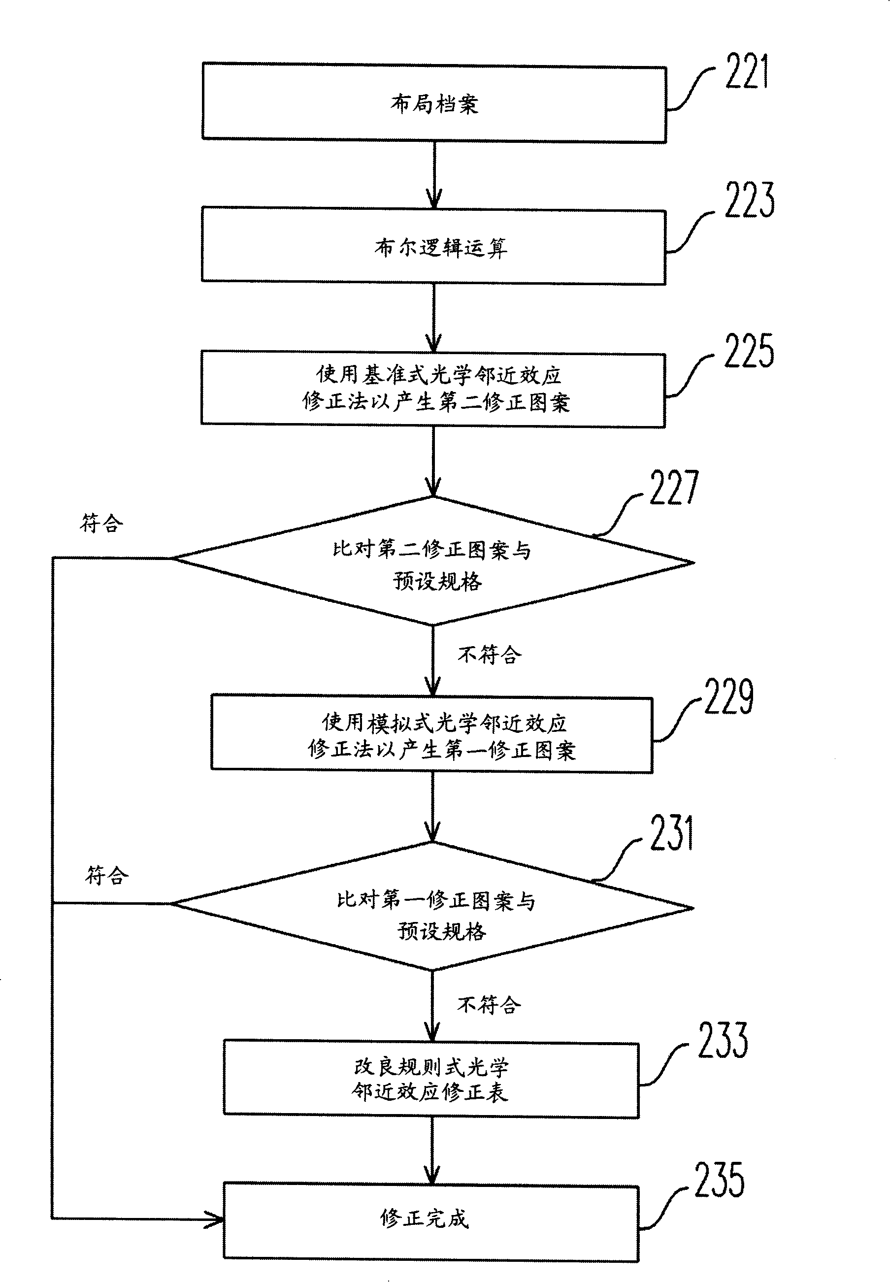
[0045] Figure 2A It is a flow chart of a hybrid optical proximity effect correction method according to an embodiment of the present invention. Please refer to Figure 2A , first receive a layout file (step 201), the layout file is used to describe the geometry of the IC layout pattern, that is, the original pattern to be transferred. Boolean logic operations are the...


PUM


Abstract

A correction method for a photo mask pattern determines an allocation condition according to interspace and linewidth of the allocation patterns, determines which optical proximity effect correcting method is used in which region by using the allocation condition, and performing a comparison by using a preset format and a corrected pattern. In addition, special allocation patterns are corrected by using a modified formal style optical proximity effect accuracy table. Thereby, both the correction accuracy and the correction speed are increased.

Description

technical field [0001] The invention relates to a method for correcting a photomask pattern, in particular to a method for correcting a hybrid photomask pattern. Background technique [0002] Today, with the vigorous development of integrated circuits (Integrated Circuit, IC), the miniaturization and integration of components is an inevitable trend, and it is also an important topic for the active development of all walks of life. In the entire semiconductor process, lithography can be said to be one of the most important steps. First, the accuracy of transferring the photomask pattern to the wafer (wafer) plays a very important role. If the transfer of the pattern is incorrect, it will affect the critical dimension (CD) tolerance (tolerance) on the chip and reduce the resolution of the exposure. [0003] With the gradual increase of integration, the size of the components is gradually reduced, and the distance between the components must also be reduced. Therefore, in the ...

Claims


Application Information

Patent Timeline
Patent Type & Authority Applications(China)
IPC IPC(8): G03F1/14H01L21/30G03F1/36
Inventor 林陵杰杨春晖李潜福黄义雄
Owner UNITED MICROELECTRONICS CORP
Features
  • R&D
  • Intellectual Property
  • Life Sciences
  • Materials
  • Tech Scout
  • Unparalleled Data Quality
  • Higher Quality Content
  • 60% Fewer Hallucinations
Learn More