Magnetic suspension electric vehicle

A technology of electric vehicles and magnetic levitation, applied in electric vehicles, electric traction, vehicle parts, etc., can solve the problems of high operation and maintenance costs, low utilization rate of magnetic energy, high cost, etc., achieve saving of permanent magnets and supporting materials, and high utilization rate , promoting a smooth effect

Inactive Publication Date: 2008-08-20
刘新广
View PDF1 Cites 8 Cited by
  • Summary
  • Abstract
  • Description
  • Claims
  • Application Information

AI Technical Summary

Problems solved by technology

[0005] The purpose of the present invention is to solve the existing magnetic levitation train complex structure and technology, the actual cost is expensive, high operation and maintenance costs, difficult to apply to the transformation of existing rail traffic, limited application and other problems; overcome the existing magnetic levitation train large magnetic leakage , Low utilization rate of magnetic energy, environmental pollution caused by changing electromagnetic fields, etc., further improve technology and reduce costs

Method used


Image

  • Magnetic suspension electric vehicle
  • Magnetic suspension electric vehicle
  • Magnetic suspension electric vehicle

Examples


specific Embodiment approach 1

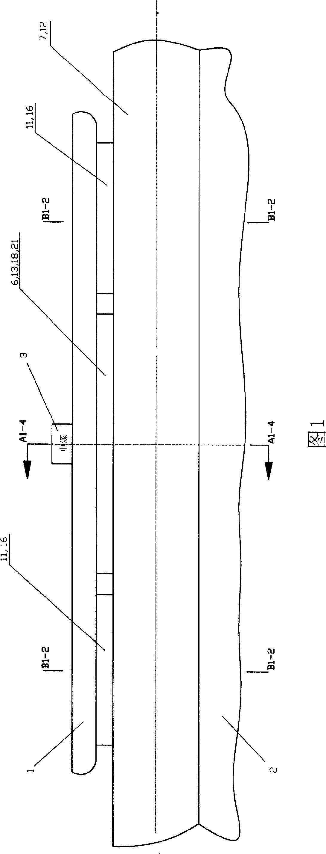
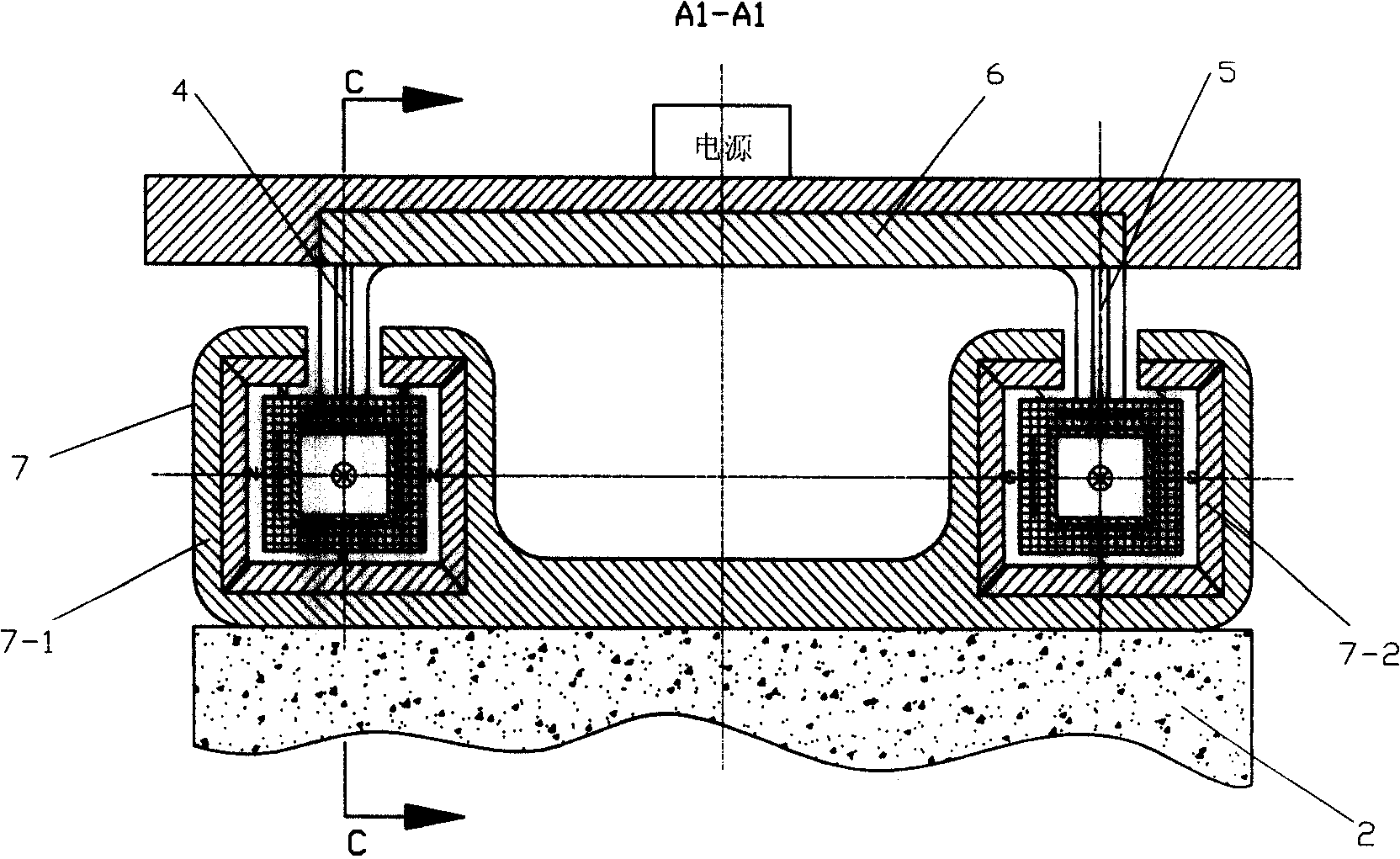
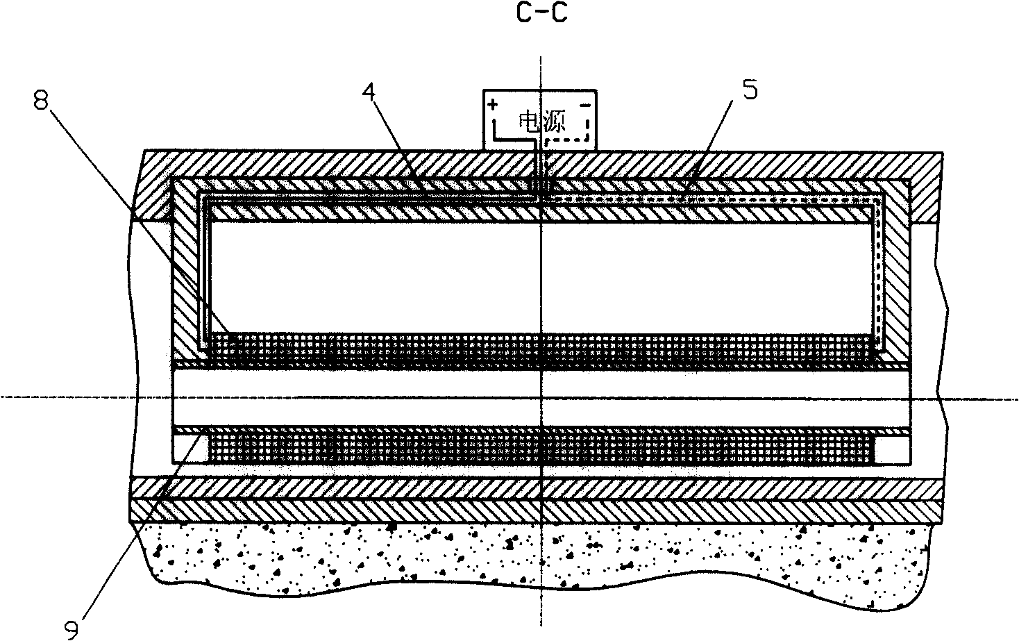
[0043] Specific embodiment one: as shown in Fig. 1 to Fig. 4 . On the non-magnetic vehicle body base plate 1, the non-magnetic support 6 that is fixedly connected to the coil frame 9, the cross section of the coil frame 9 is made into a rectangular tube shape, the inner wall of the rectangular tube is concentric with the peripheral surface and is parallel to the center line of the tube, the coil frame 9 Both ends are affixed to the bobbin support 6, and an insulated sheathed wire is wound on the peripheral surface of the bobbin 9, and the coil 8 cross-sectional profile is rectangular, and the peripheral surface of the coil 8 is parallel to the peripheral surface of the bobbin 9 and concentric; the input and output ends of the coil 8 are respectively connected to the positive pole and the negative pole of the power supply 3 with insulating sheathed wires 4 and 5. The flow direction of the current in the extension direction section is opposite; the permanent magnet plate 7-2 mag...

specific Embodiment approach 2

[0045] Specific implementation mode two: as shown in Figure 1, Figure 5 to Figure 7 shown. The inner wall of the track seat, the track permanent magnet, and the cross-section of the car body permanent magnet are all made into a circle with a gap above, and the cross-sections of the coil frame, coil, car body magnetic frame and the car body permanent magnet are all made Circular, that is, the track seat is 12-1, the track permanent magnet is 12-2, the bobbin is 14, the coil is 15, and the car body permanent magnet is 17. Its manufacturing method and requirements are the same as in the specific embodiment one, and other Also the same as the first embodiment, the track member is 12, the coil frame bracket is a non-magnetic bracket 13, and the vehicle body magnetic frame is 16.

[0046] The suspension, guidance, and propulsion principles of the car are the same as those described in the specific embodiment one.

specific Embodiment approach 3

[0047] Specific implementation mode three: as shown in Figure 1, Figure 8 to Figure 11. The vehicle body bottom plate 1, the track member 7, the vehicle body permanent magnet 10, and the vehicle body magnetic frame 11 in the specific embodiment one are kept unchanged, and the coil 8 and the coil former 9 in the specific embodiment one are replaced with a cross section of The notched rectangular conductive ring 19-1 and the notched rectangular insulating and heat-conducting ring 19-2, the conductive ring 19-1 and the insulating and heat-conducting ring 19-2 are combined and consolidated into one body along the extending direction of the track, under the vertical surface of the notch Part of the conductive strip 19-3 is consolidated along the length direction, and the conductive ring 19-1, the insulating heat-conducting ring 19-2, and the conductive strip 19-3 form a combined conductor 19; Magnetic support 18, the upper part of the vertical surface of the combined conductor 19...


PUM


Abstract

The invention relates to a maglev electric vehicle, which is characterized in that: a coil or a combined electric conductor and a plurality of vehicle body permanent magnet plates with the same peripheral polarity are arranged on the vehicle bottom plate, and the coil, or the combined electric conductor and the vehicle body permanent magnet plates shun each other along the lengthwise direction of the vehicle; a rail fixed on a road foundation is arranged right below the coil, the electric conductor as well as the permanent magnet plates; the cross section of a magnetic rail chair is a ring with an opening on the upper part, a plurality of rail permanent magnet plates magnetized along the thickness direction are fixedly connected on the internal wall of the magnetic rail chair, and the permanent magnet plates enclose the coil or the combined electric conductor and the vehicle permanent magnet plates at intervals; the rail permanent magnet plates and the vehicle permanent plates are opposite in parallel with like polarity, and the coil is connected with a direct current power supply. The vehicle is levitated and guided due to the magnetic repulsion force, and the electric vehicle is propelled forward by means of the electromagnetic action generated between the electrified coil or the electrified combined electric conductor and the rail. The maglev electric vehicle has the advantages of simple structure, less magnetic leakage, higher utilization rate of the magnets, no iron loss, no pollution due to the changeable electromagnetic field, low manufacturing costs, and easy popularization.

Description

technical field [0001] The invention relates to a magnetic levitation vehicle, in particular to a magnetic levitation electric propulsion vehicle. Background technique [0002] Magnetic levitation vehicles have excellent performances such as non-contact, low vibration, low noise, safety, speed, low energy consumption, and high efficiency. The maglev train technology in Japan and Germany is at the forefront, especially the maglev train in Germany has been extended to commercial operation. According to the levitation mode, the maglev vehicles are divided into suction-floating type and repelling-floating type. Germany adopts the constant conduction suction floating type, while Japan adopts the superconducting repellent floating type. The so-called constant guiding suction floating type is to use the electromagnet set on the train to attract the magnetic track set under the roadbed, so that the train is suspended and guided, and it is propelled by a synchronous or asynchronous...

Claims


Application Information

Patent Timeline
Patent Type & Authority Applications(China)
IPC IPC(8): B60L13/10
Inventor 刘新广
Owner 刘新广
Why Eureka
Try Eureka