Plasma flat plate light source

A flat light source, plasma technology, applied in the direction of gas plasma lamps, etc., can solve the problems of short medium discharge path and difficult to generate positive column discharge, and achieve the effect of improving luminous efficiency, luminous efficiency and brightness

Inactive Publication Date: 2008-08-20
SOUTHEAST UNIV
View PDF0 Cites 3 Cited by
  • Summary
  • Abstract
  • Description
  • Claims
  • Application Information

AI Technical Summary

Problems solved by technology

[0003] The purpose of the present invention is to solve the problem that the discharge path of the existing plasma flat light source is short and it is difficult to generate positive column discharge. The present invention provides a plasma flat light source that can improve luminous efficiency and brightness

Method used


Image

  • Plasma flat plate light source
  • Plasma flat plate light source
  • Plasma flat plate light source

Examples


Embodiment Construction

[0024] The present invention will be further described below in conjunction with the accompanying drawings and embodiments.

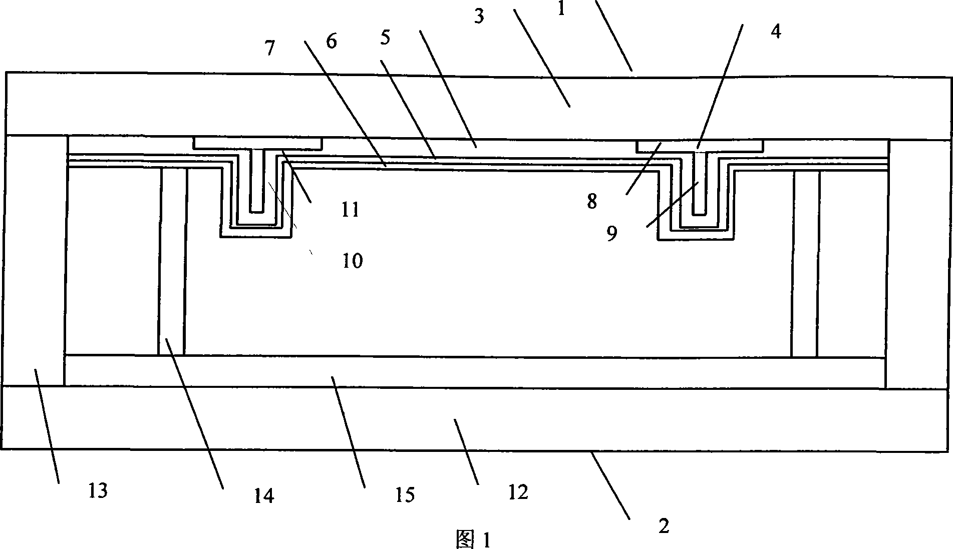
[0025] As shown in Figures 1 to 6, a plasma panel backlight with a three-dimensional three-dimensional electrode structure includes a front substrate 1 and a rear substrate 2, and the front substrate 1 is mainly composed of a front substrate glass substrate 3, a three-dimensional electrode 4, Dielectric layer 5, thin phosphor layer 6, and protective film 7. The three-dimensional electrode consists of a planar electrode 8 on the surface of the glass substrate 3 and an electrode 9 with a certain three-dimensional shape connected to the planar electrode 8. The dielectric layer 5 covers the three-dimensional On the electrode 4, the dielectric layer 5 is composed of a dielectric layer 10 surrounding the electrode 9 and a dielectric 11 covering the surface of the planar electrode 8, a thin phosphor layer 6 is coated on the surface of the dielectric layer 5, an...


PUM


Abstract

The invention discloses a plasma flat plate light source, comprising a front substrate and a back substrate, a discharge cavity is arranged between the front substrate and the back substrate, the front substrate and/or the back substrate is equipped with a first electrode and a second electrode, which are located in the discharge cavity, the front substrate is also provided with a medium layer, the first electrode and the second electrode are located between the front substrate and the medium layer, the medium layer is provided with a protecting film, the back substrate is provided with a thick fluorescent powder layer, the first electrode and/or the second electrode consists of planar electrodes connected with three-dimensional electrode standing on the planar electrodes. According to the invention, the discharge efficiency of the plasma is improved, the brightness of the plasma light source is increased, and the lighting efficiency is also improved.

Description

technical field [0001] The invention relates to a plasma flat panel light source, in particular to a plasma flat panel light source with a novel electrode structure, in particular to a plasma flat panel light source with a three-dimensional three-dimensional structure. Background technique [0002] The light sources using the principle of plasma discharge currently include tubular fluorescent lamps and flat fluorescent lamps, among which tubular fluorescent lamps include cold cathode fluorescent lamps (CCFL) and hot cathode fluorescent lamps (HCFL). These light sources have high luminous efficiency and constitute liquid crystal displays. The main products of the backlight source, because they are tubular line light sources, in order to meet the requirements of the surface light source, it is necessary to add a reflector on the back of the light source module, a light guide plate and a uniform light plate in the front, so that the luminous brightness is greatly lost. The use ...

Claims


Application Information

Patent Timeline
Patent Type & Authority Applications(China)
IPC IPC(8): H01J63/08
Inventor 李青罗瑶吉志坚张雄屠彦汤勇明郑姚生杨兰兰崔渊
Owner SOUTHEAST UNIV
Why Eureka
Try Eureka