Non-aqueous electrolyte secondary battery

A non-aqueous electrolyte, secondary battery technology, applied in non-aqueous electrolyte batteries, non-aqueous electrolyte battery electrodes, secondary batteries, etc., can solve the problem of inability to effectively use battery shell space, increase in electrode group diameter, cycle characteristics and reliability. Sexual decline, etc.

Inactive Publication Date: 2008-08-20
PANASONIC CORP
View PDF1 Cites 0 Cited by
  • Summary
  • Abstract
  • Description
  • Claims
  • Application Information

AI Technical Summary

Problems solved by technology

[0009] However, the diameter of the electrode group increases due to the expansion of the negative electrode material caused by the intercalation of lithium ions. Therefore, considering the change in the shape of the electrode group in advance, the electrode group must be made small so that it can be accommodated in a battery case. middle
Therefore, the space in the battery case cannot be effectively used, and there is a problem that the improvement of the battery capacity is limited.
Moreover, the size of the secondary battery is limited by the size of the battery case, and therefore, a large stress is generated on the columnar negative electrode material due to the expansion of the electrode group.
In addition, since the columnar negative electrode material is bonded to the current collector especially at the convex portion, stress is concentrated on the joint portion, and there is a problem that the columnar negative electrode material is peeled off from the current collector.
In addition, wrinkling and deformation may occur on the current collector even without peeling
As a result, cycle characteristics and reliability are sometimes degraded

Method used


Image

  • Non-aqueous electrolyte secondary battery
  • Non-aqueous electrolyte secondary battery
  • Non-aqueous electrolyte secondary battery

Examples


Embodiment approach 1

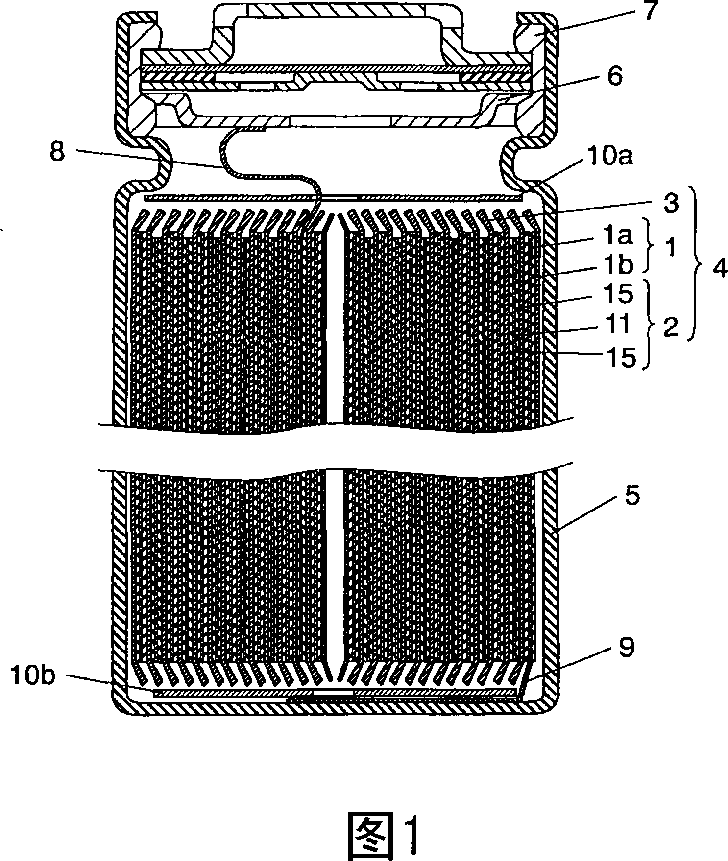
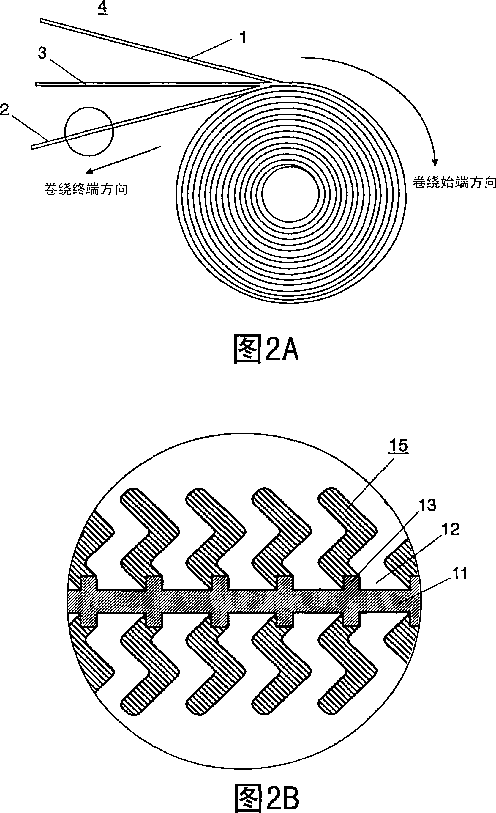
[0037] 1 is a cross-sectional view of a nonaqueous electrolyte secondary battery in Embodiment 1 of the present invention; FIG. 2A is a plan view schematically showing a wound state of an electrode group of a nonaqueous electrolyte secondary battery in Embodiment 1 of the present invention; FIG. 2B is a partially enlarged cross-sectional view illustrating in detail the structure of the negative electrode of FIG. 2A .

[0038] As shown in FIG. 1 , a cylindrical nonaqueous electrolyte secondary battery (hereinafter referred to as "battery") has an electrode group 4 in which a separator 3 is inserted into a positive electrode 1 having a positive electrode lead 8 made of aluminum, for example. It is wound as shown in FIG. 2A between the negative electrode 2 facing the positive electrode 1 and having a negative electrode lead 9 made of copper at one end. And, the insulating plates 10a, 10b are installed on the upper and lower sides of the electrode group 4, then inserted in the bat...

Embodiment approach 2

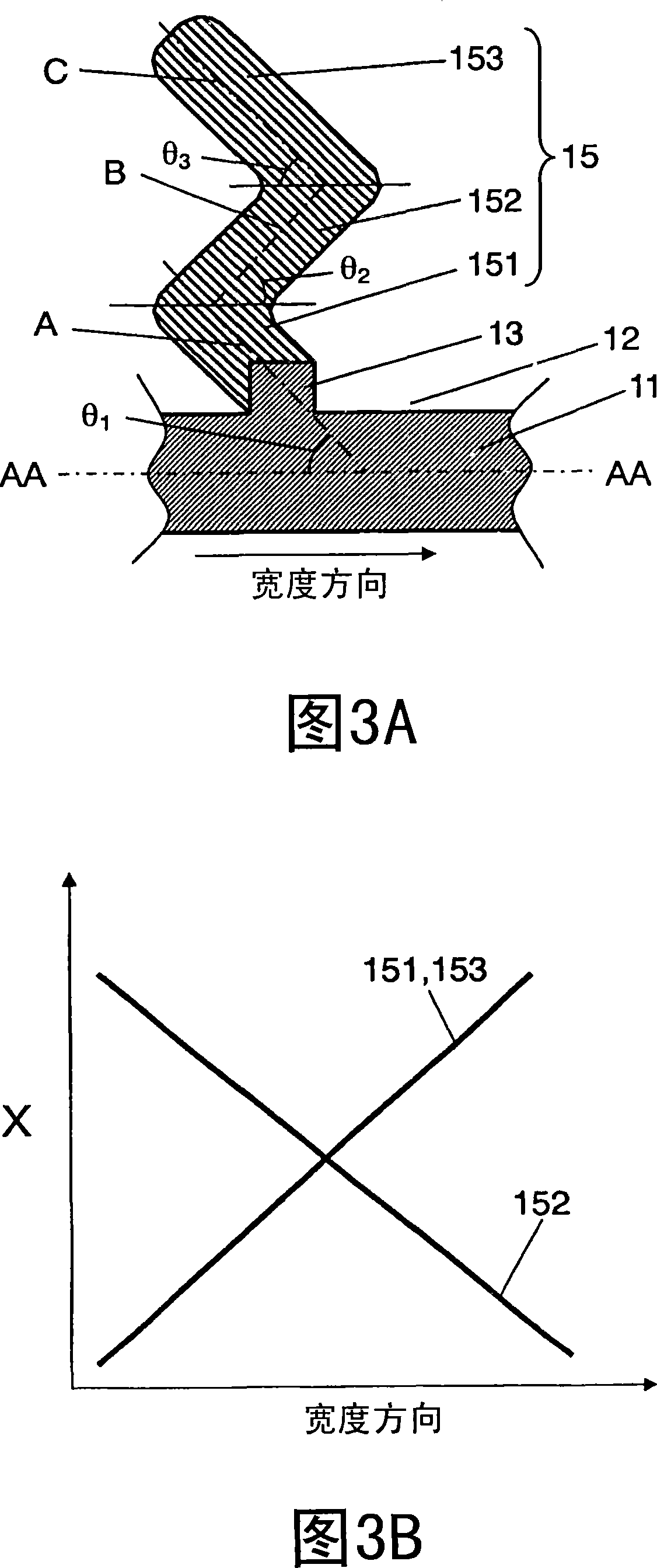
[0082] 9A is a partially enlarged cross-sectional view showing the structure of the negative electrode according to Embodiment 2 of the present invention; FIG. 9B is a schematic diagram illustrating changes in x values ​​in the width direction of active materials constituting each columnar body part according to Embodiment 2 of the present invention. In addition, in this embodiment, since the cylindrical battery similar to FIG. 1 is used, detailed description is abbreviate|omitted. In addition, the constituent materials of the positive electrode mixture layer, the positive electrode current collector, the negative electrode current collector, and the columnar body are also the same as those in Embodiment 1, and thus detailed description thereof will be omitted.

[0083] The difference between this embodiment and Embodiment 1 is that in this embodiment, the entire columnar body composed of n=7 columnar body parts is placed on the convex part of the current collector and obliquel...

Embodiment 1

[0104] The columnar body of the negative electrode was produced using the production apparatus shown in FIG. 8 .

[0105] First, as a current collector, a strip-shaped electrolytic copper foil having a thickness of 30 μm was used on the surface of which protrusions were formed at intervals of 20 μm by a plating method.

[0106] Then, using Si as the active material of the negative electrode, using an evaporation unit (integrated by an evaporation source, a crucible, and an electron beam generator), the oxygen with a purity of 99.7% is introduced into the vacuum container from the oxygen introduction nozzle, Made of SiO x Constructed one-stage columnar body part whose x value changes in the width direction. At this time, an oxygen atmosphere at a pressure of 3.5 Pa was formed inside the vacuum vessel. In addition, during vapor deposition, the electron beam generated by the electron beam generator is deflected by the deflection yoke and irradiated onto the vapor deposition sou...


PUM

PropertyMeasurementUnit
Thicknessaaaaaaaaaa
Densityaaaaaaaaaa
Thicknessaaaaaaaaaa

Abstract

A non-aqueous electrolyte secondary battery comprising at least a negative electrode having a current collector provided thereon with convex portions and columnar bodies formed on the convex portions, each of the columnar bodies comprising n stages (where n>=2) of overlaid columnar body portions alternately tilted to different orientations along a longitudinal direction of the current collector, a positive electrode having a positive electrode current collector provided on both surfaces thereof with a positive electrode mixture layer containing a positive electrode active material capable of inserting and extracting lithium ions reversibly, and a separator interposed between the positive electrode and the negative electrode in a confronting manner, wherein tip portions of the columnar body portions at the uppermost stage of the columnar bodies on the negative electrode are tilted toward a trailing end of winding direction.

Description

technical field [0001] The present invention relates to a cylindrical non-aqueous electrolyte secondary battery, and specifically relates to the structure of the negative electrode of the battery. Background technique [0002] In recent years, as electronic devices have become more portable and cordless, secondary batteries such as nickel metal hydride or lithium ion, which are small, lightweight, and have high energy density, have attracted attention as power sources for driving them. [0003] A lithium ion secondary battery includes: a positive electrode formed of a lithium-containing composite oxide, a negative electrode containing metal lithium or a lithium alloy, or a negative electrode active material capable of intercalating and deintercalating lithium ions, and an electrolyte. [0004] Moreover, in recent years, it has been reported about lithium ion intercalation and theoretical capacity density exceeding 833mAh / cm 3 Elements to replace carbon materials such as gra...

Claims


Application Information

Patent Timeline
IPC IPC(8): H01M4/02H01M10/40H01M4/13H01M4/131H01M4/134H01M4/48H01M4/70H01M10/052H01M10/0525H01M10/0587
CPCY02E60/122Y02E60/10Y02P70/50
Inventor 白根隆行井上薰宇贺治正弥藤川万乡佐藤俊忠
Owner PANASONIC CORP
Why Eureka
Try Eureka