Drive device for vehicle

A vehicle driving device and driving wheel technology, which is applied in the transmission device, power device, gear transmission device, etc., and can solve the problems of difficult lubricating oil passage, complicated connection structure of the first shaft, and complicated structure.

Inactive Publication Date: 2008-08-20
TOYOTA JIDOSHA KK
View PDF1 Cites 21 Cited by
  • Summary
  • Abstract
  • Description
  • Claims
  • Application Information

AI Technical Summary

Problems solved by technology

Thus, it becomes difficult to provide a lubricating oil passage for supplying lubricating oil to the oil passage extending longitudinally through the rotating shaft.
If an attempt is made to form a lubricating oil passage in a cover formin

Method used


Image

  • Drive device for vehicle
  • Drive device for vehicle
  • Drive device for vehicle

Examples


Embodiment 1

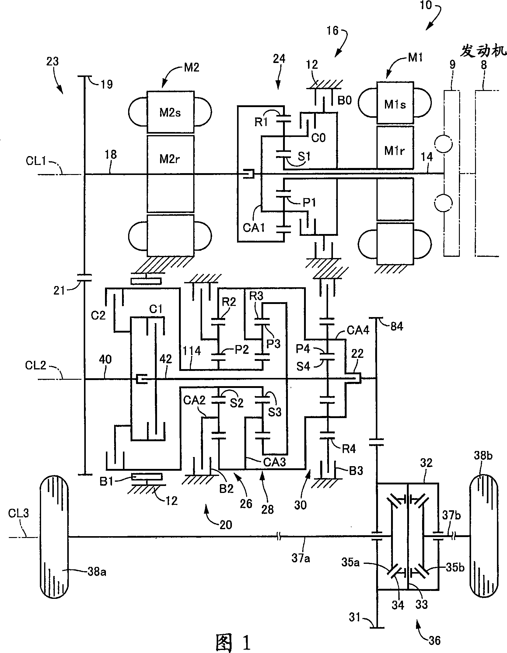
[0153] First, refer to the schematic diagram of FIG. 1, which shows a driving device 10 for a hybrid vehicle constructed according to an embodiment of the present invention. The driving device 10 shown in FIG. 1 includes: an engine 8; a transaxle housing 12 (hereinafter referred to as "housing 12"), which is a fixed member installed on the vehicle body; a pulsation absorbing damper (vibration damping device) 9; The first input shaft, which is in the form of an input rotating member 14 connected to the engine 8 via a pulsation absorbing damper 9 and receiving the output of the engine 8 via a pulsation absorbing damper 9 (vibration damping device); a first electric motor M1; a hydraulic operation type Differential limiting device, which is in the form of switching clutch C0 and switching brake B0; differential gear mechanism or differential part, which is in the form of power distribution mechanism 16 connected to input rotating member 14; power transmission member 18, its configura...

no. 1 example

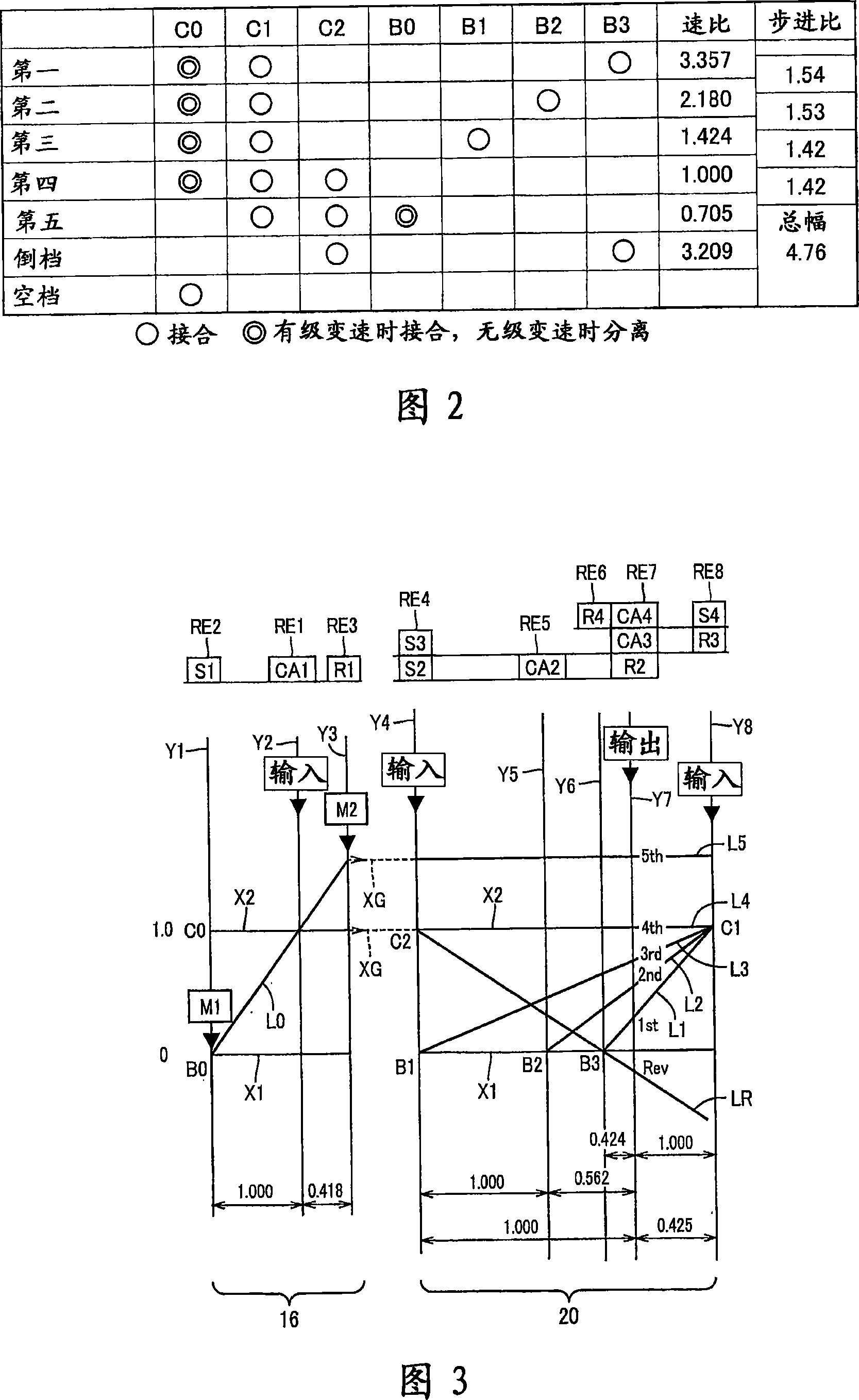
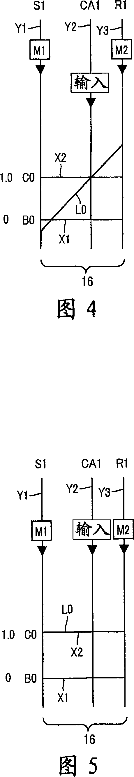
[0245]According to the first embodiment, the driving device 10 includes a power distribution mechanism (differential portion) 16 and a second electric motor M2, and the driving force applied to the input rotating member 14 is distributed to the first electric motor M1 and the power transmission member via the power distribution mechanism 16 18. The second electric motor M2 is arranged in the power transmission path between the power transmission member 18 and the drive wheels 38a, 38b. In addition, the drive device 10 includes an automatic transmission portion (transmission portion) 20 arranged between the power transmission member 18 and the drive wheels 38a, 38b. The first electric motor M1 and the power distribution mechanism (differential portion) 16 are sequentially arranged from the input rotation member 14 side on the first axis CL1 forming the rotation axis of the input rotation member 14, and the automatic transmission portion (transmission portion) 20 is arranged on On t...

Embodiment 2

[0275] Other embodiments of the present invention will be described below. In the following description of the other embodiments, the same reference numerals as in the first embodiment are used to denote elements with the same functions, and redundant descriptions thereof will be omitted.

[0276] Refer to the partial cross-sectional view of FIG. 19, which shows a part of the vehicle drive device 186 according to the second embodiment of the present invention. The driving device 186 is different from the driving device 10 of the first embodiment only in that a driving connection device 188 is provided instead of the driving connection device 23. As shown in FIG. 19, the driving connection device 188 includes a driving sprocket 190, a driven sprocket 192 and a transmission belt 194. The transmission belt 194 is made of metal or resin and connects the driving sprocket 190 and the driven sprocket 192. The driving sprocket 190 is mounted on the axial end of the power transmission memb...


PUM


Abstract

Provides small vehicle drives with reduced axial dimensions without increasing the number of parallel shafts. The first electric motor (M1) and the power distributing mechanism (differential part) (16) are arranged on the first axis (CL1) which is the rotation center of the input rotating member (14) in order from the input rotating member (14), automatically The transmission (transmission unit) (20) is arranged on a second axis (CL2) parallel to the first axis (CL1). The transmission member (18), which is a rotating member located on the first axis (CL1) at the end opposite to the input rotating member (14), and arranged on the second axis at the end opposite to the input rotating member (14) Between the first intermediate shaft (rotating member) (40) on (CL2), a driving connection device (23) is provided to be able to transmit power. In this way, the power transmission path becomes a C-shape or a U-shape with reduced axial dimension, which can reduce the size and simplify the structure without increasing parallel shafts.

Description

Technical field [0001] The present invention relates to a vehicle drive device having a first motor, a differential device, a second motor and a transmission, a vehicle drive device having a motor, a differential portion and a differential drive gear mechanism (differential drive gear), or a A vehicle drive device with an input shaft, an electric motor, a differential portion, and a transmission portion. More specifically, the present invention relates to a technique for reducing the axial size of a vehicle drive device while improving assembly performance, a technique for enhancing the cooling characteristics of an electric motor, and a technique for simplifying the structure of a hydraulic circuit. Background technique [0002] A vehicle drive device having a first electric motor, a differential device, a second electric motor, and a transmission has been known. For example, the hybrid vehicle drive device disclosed in Patent Document 1 is such a drive device. In the device dis...

Claims


Application Information

Patent Timeline
IPC IPC(8): B60K11/06B60K17/04F16H3/72B60L11/14F16H1/08F16H3/66F16H57/02F16H57/04B60K6/26B60K6/365B60K6/40B60K6/445B60K6/547B60L50/16F02D29/02F02D29/06
CPCY02T10/62Y02T10/7072
Inventor 田端淳宫崎光史镰田淳史多贺丰
Owner TOYOTA JIDOSHA KK
Why Eureka
Try Eureka