
Optical cable and transmitting/receiving sub-assembly

A technology for transmitting and receiving components and optical cables, which is applied in the direction of optical components, optics, light guides, etc., to achieve the effects of increased design freedom, high-density installation, and improved production efficiency

Inactive Publication Date: 2008-08-20
MITSUMI ELECTRIC CO LTD
View PDF2 Cites 0 Cited by
  • Summary
  • Abstract
  • Description
  • Claims
  • Application Information

AI Technical Summary

Problems solved by technology

Therefore, there is a problem that the optical transmission loss in the coupling optical path is generated a lot

Method used


Image

  • Optical cable and transmitting/receiving sub-assembly
  • Optical cable and transmitting/receiving sub-assembly
  • Optical cable and transmitting/receiving sub-assembly

Examples


Embodiment Construction

[0034] (Structure of optical cable and connector part)

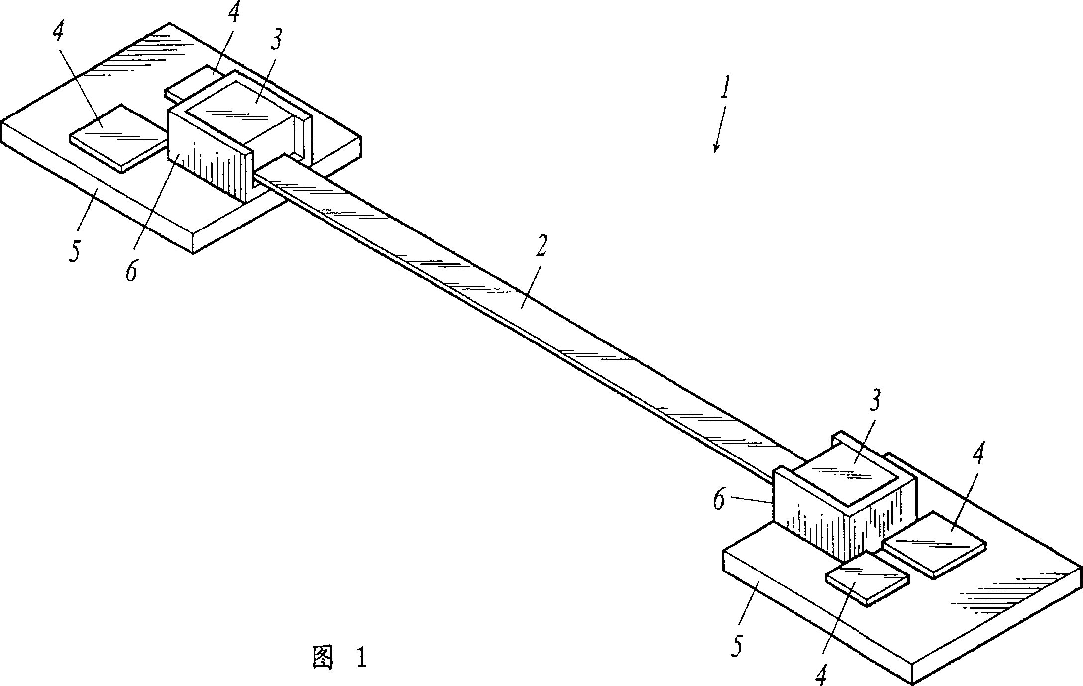
[0035] FIG. 1 shows the structure of an optical cable 1 according to this embodiment.

[0036] As shown in FIG. 1 , an optical cable 1 is a component for connecting two printed wiring boards 5 , and is configured to include connectors 3 at both ends of an optical waveguide cable 2 . The connector 3 is mounted on the socket 6 mounted on the printed wiring board 5 , and the IC 4 is additionally mounted on the printed wiring board 5 .

[0037] The optical waveguide cable 2 is formed in a film shape, and the optical waveguide included therein functions as a transmission path for light exchanged between connectors 3 provided at both ends. The connector 3 is equipped with a transceiver component for photoelectric conversion, and the transceiver component converts the electrical signal input from the printed circuit wiring substrate 5 into light, and sends the light to the connector 3 on the other end side by means of the opti...


PUM


Abstract

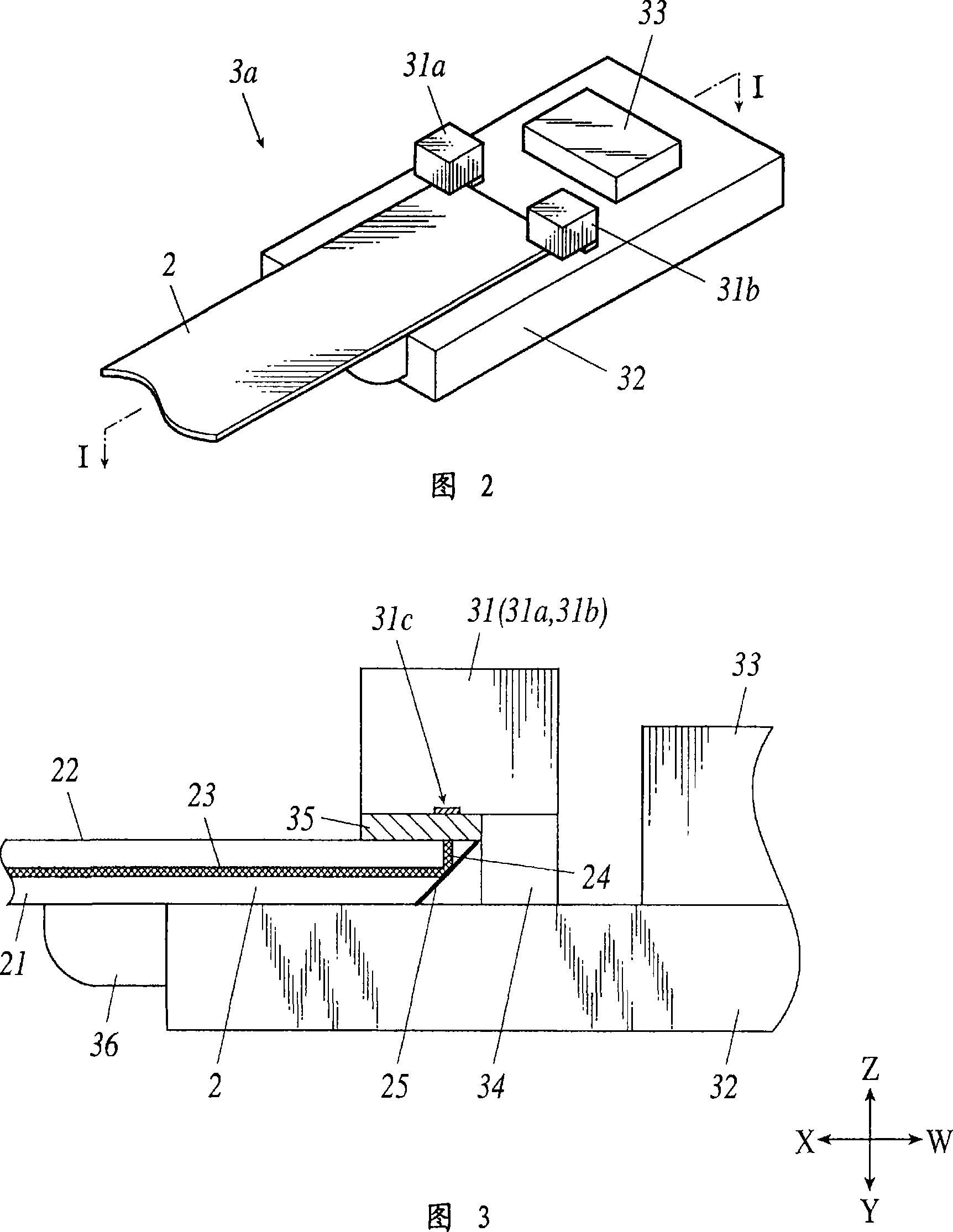
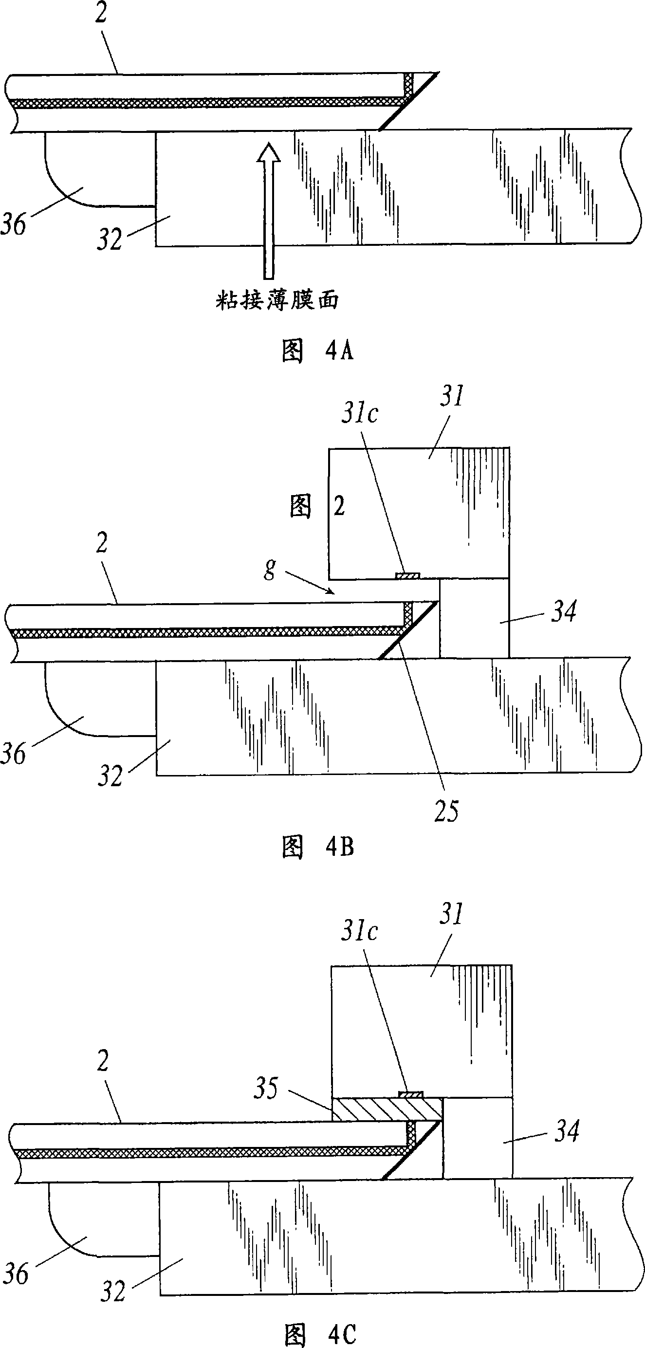
The invention provides an optical cable and a transceiver assembly with high design freedom and high optical coupling rate. In the transceiver assembly (3a) of the connector (3), on its auxiliary substrate (32), the photoelectric conversion element (31) is provided with a space between the mounting surface and the mounting surface by means of a bump (34) and is arranged. The optical waveguide cable (2) is arranged in this space. The height of the photoelectric conversion element (31) relative to the mounting surface is determined according to the thickness of the optical waveguide cable (2), and its height position is controlled by adjusting the size of the bump (34).

Description

technical field [0001] The invention relates to an optical cable for optical transmission through an optical waveguide and a transceiver assembly. Background technique [0002] In recent years, the development of an optical cable in which an optical waveguide is formed on a film-shaped cable has been advanced (for example, refer to Patent Document 1: JP-A-2001-166167; Patent Document 2: JP-A-2004-361858). On the connector part mounted on the socket of this optical cable, from the viewpoint of reducing power consumption or multi-channel, a surface-type light-emitting element (hereinafter referred to as VCSEL; Vertical Cavity Emitting Laser) or PD (Photo Diode) is mounted. and other photoelectric conversion elements. [0003] 7 and 8 show a conventional configuration of a transceiver module in a connector mounted with a VCSEL, a photoelectric conversion element of a PD, and a film optical waveguide cable. FIG. 7 is a perspective view, and FIG. 8 is a cross-sectional view tak...

Claims


Application Information

Patent Timeline
Patent Type & Authority Applications(China)
IPC IPC(8): G02B6/42G02B6/44
CPCG02B6/4214G02B6/4228G02B6/42
Inventor 小野位石川贵启
Owner MITSUMI ELECTRIC CO LTD
Learn More