Cereal flow measuring device of combine-harvester and yield measure method of combine-harvester

A technology of combine harvester and measuring device, applied in the direction of measuring device, harvester, weighing, etc., can solve the problems of mass flow measurement accuracy, humidity and moisture content, unreliable work, complex structure, etc., to eliminate grain The effect of different surface moisture content, simple and reliable use, and accurate yield information

Inactive Publication Date: 2008-08-27
JIANGSU UNIV
View PDF2 Cites 42 Cited by
  • Summary
  • Abstract
  • Description
  • Claims
  • Application Information

AI Technical Summary

Problems solved by technology

The defect of these two patent applications is that the output value does not take into account the influence of air humidity and grain moisture content during harvesting, and is not comparable to the standard crop yield measured under standard air humidity and grain moisture content. At the same time, the output value and the harvested area Similarly, it is not scientific and reasonable as the basis for the harvesting cost of the harvester
This kind of flow measurement device can achieve quite high accuracy and good real-time performance, but it needs to add a larger scraper wheel mechanism and its driving motor between the grain elevator outlet and the ba

Method used


Image

  • Cereal flow measuring device of combine-harvester and yield measure method of combine-harvester
  • Cereal flow measuring device of combine-harvester and yield measure method of combine-harvester
  • Cereal flow measuring device of combine-harvester and yield measure method of combine-harvester

Examples


Example Embodiment

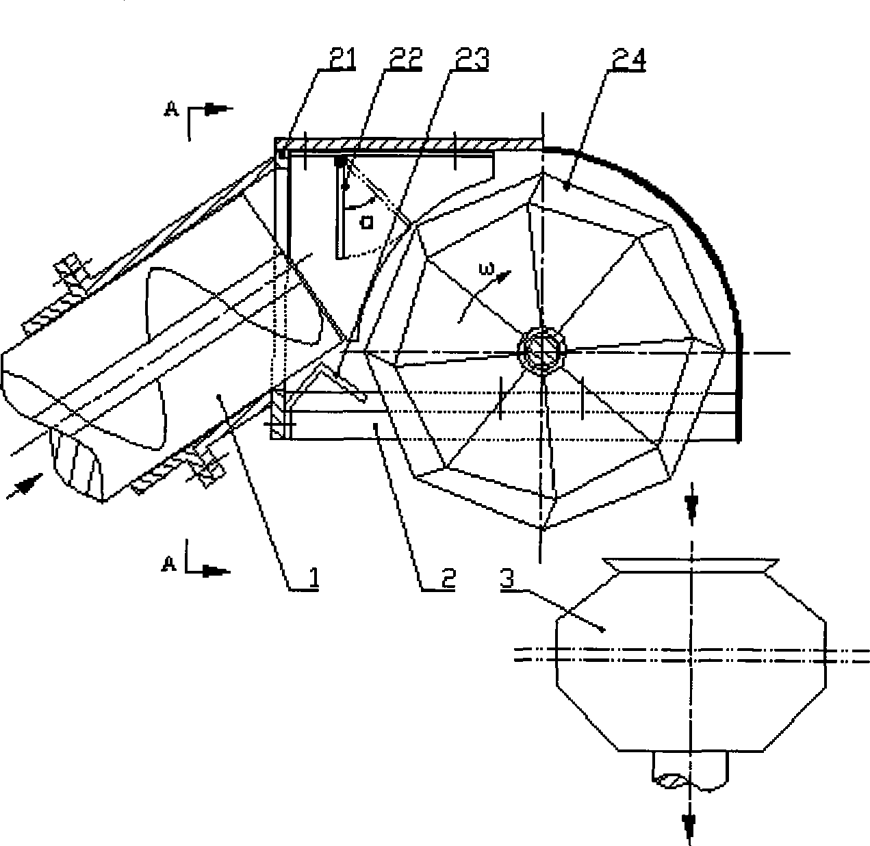
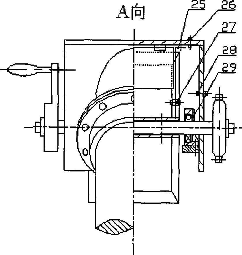
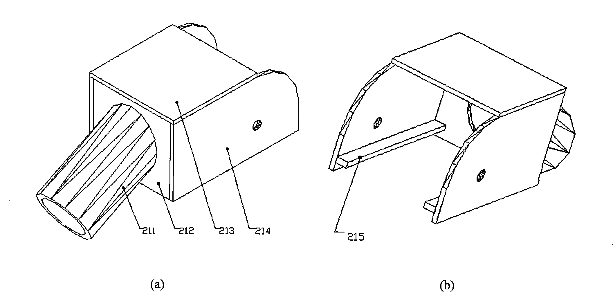
[0026] Such as Figure 1~3 As shown, the outlet of the stirring cage 1 is connected to the inlet of the measuring device 2, the outlet of the measuring device 2 is above the barn 3, and the grains are discharged from the stirring cage 1 through the measuring device 2 and then thrown into the barn 3. The measuring device 2 includes a casing 21. An upper baffle mechanism 22 and an air humidity sensor 26 are installed above the casing 21, a lower baffle 23 is installed below, side baffles 25 are installed on both sides of the front and rear, and the front is installed to support the bearing component 29 for measurement Axle member 24; a grain humidity sensor 27 is installed at the lower part of the side baffle 25, and a proximity switch 28 is installed on the side close to the metering axle member 24. The air humidity sensor 26, the grain moisture content (or humidity) sensor 27, the proximity switch 28 and the counting interface are connected to the microcomputer system.

[0027] Th...


PUM


Abstract

The invention discloses a grain flow measurement device and a production measurement method thereof for a combine harvester. A screw outlet is connected to an inlet of the measurement device; an outlet of the measurement device is on the top of a barn, the grain is discharged by the screw and thrown to the barn after passing through the measurement; an air humidity sensor, a grain humidity sensor and a proximity switch interface are respectively connected to a microcomputer system; the relation of the standard quality flow of the grain with the air humidity of the harvest field, the water content of the grain and the capacity flow of the grains is firstly established, then the grain is input to the measurement device to be detected the reaping parameters online by various sensors and the proximity switch through the microcomputer, and eventually, the standard quality flow, the yield and the overall yield of the harvest grain are calculated. The measurement of the device has the advantages of little impact by the working environment, high accuracy, compact structure, simple and reliable use and low cost, which not only eliminates the impact of different inner and surface water content of the grain to crop yield caused by air humidity in harvest, but also provides accurate yield information for implementing fine agricultural production.

Description

technical field [0001] The invention relates to a grain flow measuring device and yield measuring method of a combine harvester, belonging to the technical field of measuring devices, and used for online measurement of grain flow and harvested crop yield during the harvesting process of a combine harvester. Background technique [0002] During the grain harvesting process, the crop yield and its spatial distribution information (yield map) collected online concentratedly reflect the influence of farmland soil characteristics, fertilizer use, topographic structure, meteorological factors, irrigation conditions, and Cordyceps infestation on yield. It can not only provide decision-making basis for subsequent variable operations, but also feedback the implementation effect of previous precision farming links, making precision agriculture a complete closed-loop adjustment system. Therefore, crop yield is important information that needs to be obtained in precision agriculture, an...

Claims


Application Information

Patent Timeline
IPC IPC(8): A01D41/127G01G11/00
Inventor 张西良李萍萍陈树人毛翠云李耀明李伯全张夏蓉张卫华胡永光王纪章袁俊杰张锋张建
Owner JIANGSU UNIV
Why Eureka
Try Eureka