Iron melt transfer system

A technology of molten iron and molten iron tank car, which is applied in the direction of casting molten material containers, manufacturing tools, foundry workshops, etc., which can solve the problems of increasing heat loss, large floor space, and large temperature drop of molten iron, so as to improve transportation speed and floor space Small, reduce the effect of molten iron temperature drop

Inactive Publication Date: 2010-06-23
CHONGQING IRON & STEEL (GRP) CO LTD
View PDF5 Cites 2 Cited by
  • Summary
  • Abstract
  • Description
  • Claims
  • Application Information

AI Technical Summary

Problems solved by technology

The traditional transportation method has a long transshipment cycle and needs to wait, which increases heat loss and increases the temperature drop of molten iron
At the same time, the transfer system including the torpedo tank car occupies a large area and wastes cost

Method used


Image

  • Iron melt transfer system
  • Iron melt transfer system

Examples


Embodiment Construction

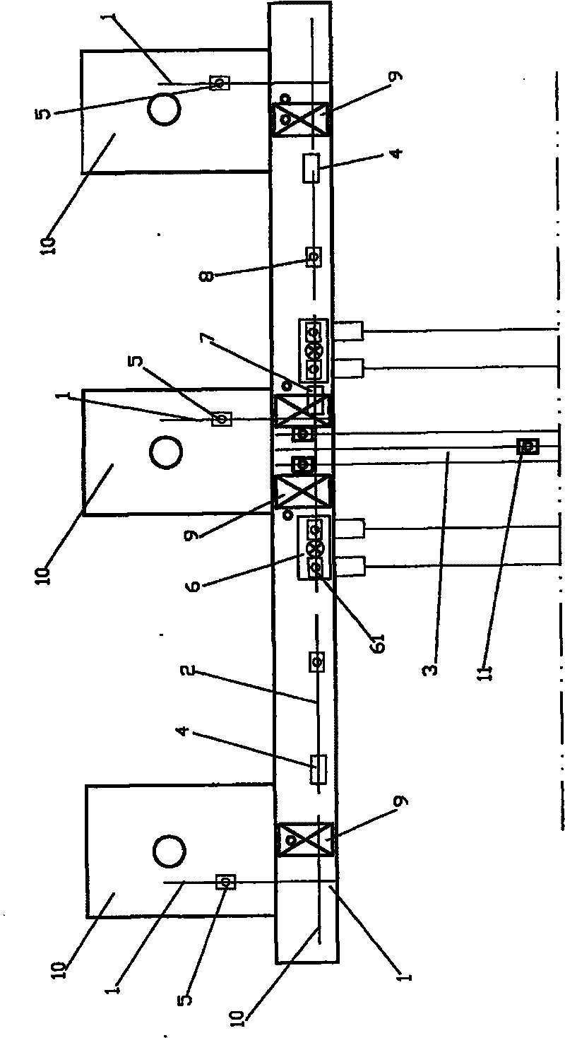
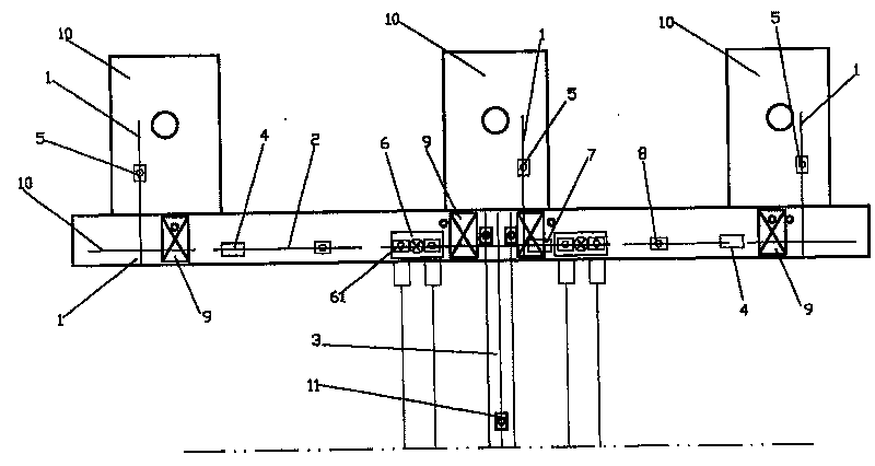
[0018] Accompanying drawing is the layout diagram of the present invention, as shown in the figure: the molten iron transfer system of the present invention comprises blast furnace molten iron transportation line I 1, molten iron transportation line II 2 between adjacent blast furnaces and goes to steelmaking workshop molten iron transportation line III3, molten iron The transportation line I 1 is arranged in a straight line between the blast furnace and the molten iron transportation line II 2, the molten iron transportation line II 2 is arranged in a straight line between two adjacent blast furnaces 3, and the molten iron transportation line III 3 is arranged in a straight line between the molten iron transportation line II 2 and the smelter. Between the steel workshops; the transfer car I 4 is set at the transition between the molten iron transportation line I 1 and the molten iron transportation line II 2, and the transfer car II7 is set at the transition between the molten ...


PUM


Abstract

The invention discloses a molten iron transport system, which comprises a first transport path of molten iron in a blast furnace, a second transport path of molten iron between adjacent blast furnaces, and a third transport path for transporting molten iron to a steel-making plant, wherein the first transport path is linearly arranged between the blast furnace and the second transport path ; the second transport path is linearly arranged between two adjacent blast furnaces; the third transport path is linearly arranged between the second transport path and the steel-making shop; a first transport vehicle is arranged at the transition position of the first transport path and the second transport path; a second transport vehicle is arranged at the transition position of the second transportpath and the third transport path; a desulfurizing station is also arranged at the transition position of the second transport path and the third transport path ; a first ground molten iron tank car,a second ground molten iron tank car and a third ground molten iron tank car are respectively arranged on the first transport path, the second transport path and the transport path third. The molten iron transport system has high transport continuity, and can maximally shorten the transport cycle and eliminate the influence of centrifugal force on the production safety in the transport process, thus improving the transport speed and reducing temperature drop of the molten iron.

Description

technical field [0001] The invention relates to a molten iron transportation system, in particular to a molten iron transfer system. Background technique [0002] The transportation of molten iron is an essential part of the ironmaking-steelmaking process. In the prior art, molten iron is transported from the blast furnace to the steelmaking plant in the form of locomotive-drawn molten iron tanks or torpedo tank cars. The gauge is narrow (1435 mm), the track is small, and there are switches and curves. The medium speed cannot be too fast, otherwise the centrifugal force generated will have an extremely adverse effect on the safety of transportation. The traditional transportation method of molten iron tanks requires grouping of tanks, which has a long operating cycle and a large temperature drop of molten iron. The traditional transportation method has a long transshipment period and needs to wait, which increases heat loss and increases the temperature drop of molten iron...

Claims


Application Information

Patent Timeline
Patent Type & Authority Patents(China)
IPC IPC(8): B22D47/00B22D41/12
Inventor 董荣华张勇谢朝忠庞勇吴银兵李克勤凌代万
Owner CHONGQING IRON & STEEL (GRP) CO LTD
Why Eureka
Try Eureka