

Automobile auxiliary current transformer
A vehicle auxiliary and inverter technology, applied in vehicle components, current collectors, electric vehicles, etc., can solve the problems of large electromagnetic interference, serious switching noise, large voltage/current spikes, etc., to meet the requirements of lightweight design, The effect of reducing switching noise and switching loss
- Summary
- Abstract
- Description
- Claims
- Application Information
AI Technical Summary
Problems solved by technology
Method used
Image

Examples
Embodiment approach 1
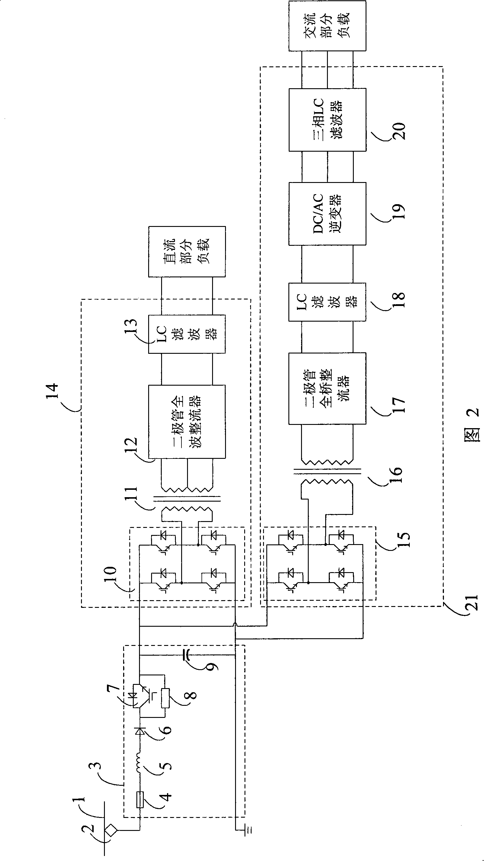
[0020] FIG. 2 shows the configuration of the main circuit of the vehicle auxiliary converter according to Embodiment 1 of the present invention. In the figure, the auxiliary converter obtains power from the overhead line 1 through the pantograph 2 . The overhead line 1 is the third rail of the overhead line or the ground.
[0021] The structure of the grid-side filtering part 3 is as follows: the diode 6 is connected to the collector of the grid-side power switch tube 7, the emitter of the grid-side power switch tube 7 is connected to the positive pole of the filter capacitor 9 to form the positive pole of the DC bus, and the soft-start resistor 8 The two ends are respectively connected to the collector of the grid-side power switch tube 7 and the emitter of the grid-side power switch tube 7 . The fuse 4 in the filter part 3 of the grid side is used to protect the auxiliary converter device, the filter reactance 5 and the filter capacitor 9 form an LC smoothing unit, and the ...
Embodiment approach 2
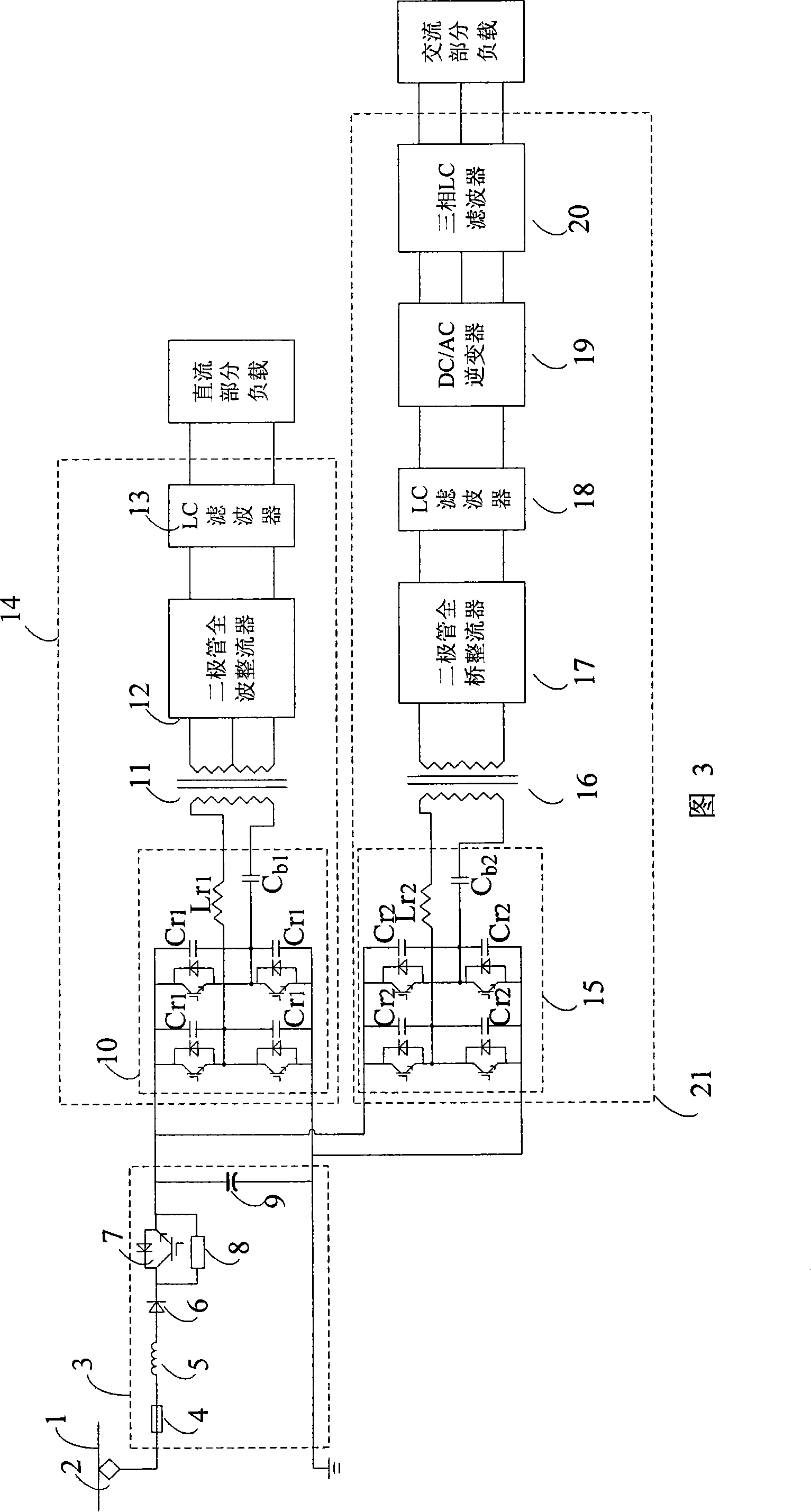
[0025] FIG. 3 shows the configuration of a main circuit of a vehicle auxiliary converter according to Embodiment 2 of the present invention. The circuit topology is basically the same as that described in Embodiment 2, except for the DC / DC chopper 10 in the DC conversion part 14 and the DC / DC chopper 15 in the AC conversion part 21 . In this embodiment, the voltage-type power switching device in the DC / DC chopper works in a state of ZVS soft switching (zero voltage soft switching).
[0026] The main circuit topology of the DC / DC chopper 10 in the DC conversion part 14 is a full-bridge chopper circuit, and a resonant capacitor C is connected in parallel at both ends of each voltage-type power switch tube in the main circuit. r1 , connect the resonant inductor L before the transformer 11 r1 and blocking capacitor C b1 , using phase-shifted full-bridge ZVS PWM control to ensure that before each power switch is turned on, the voltage across its collector and emitter is reduced t...
PUM
 Abstract
Description
Claims
Application Information