Down-hole slurry generator

A generator and mud technology, applied in the direction of engine components, machines/engines, electrical components, etc., can solve the problems of short product life, easy leakage, poor sealing, etc., and achieve the effect of long product life, reliable and stable operation

Inactive Publication Date: 2008-08-27
BEIJING TIANXING JINGZUAN TECH DEV
View PDF0 Cites 4 Cited by
  • Summary
  • Abstract
  • Description
  • Claims
  • Application Information

AI Technical Summary

Problems solved by technology

[0003] The purpose of the present invention is to provide a downhole mud generator, to solve the technical problem of stable power supply for drilling while drilling eq

Method used


Image

  • Down-hole slurry generator

Examples


Example Embodiment

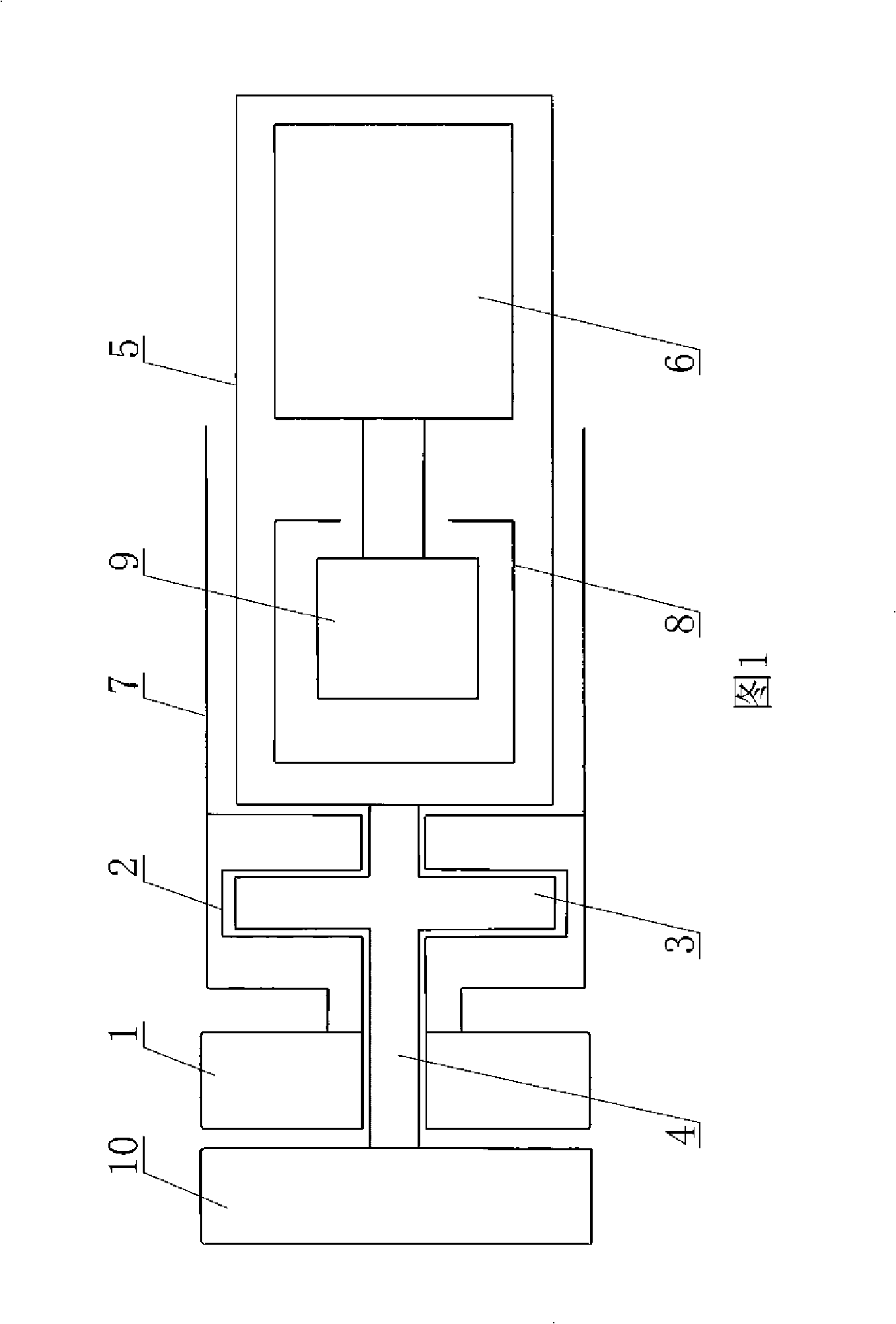
[0018] The embodiment is shown in Figure 1. In this downhole mud generator, the power is transmitted by a magnetic coupling between the turbine 1 driven by the mud and the generator body 6. The turbine 1 is connected to the magnetic coupling through a buffer clamping wall sleeve 2 The outer magnetic rotor 7 is connected, and the middle section of the inner wall of the buffer clamping wall sleeve 2 has an annular groove sunken toward the outer wall. The buffer plug 3 is accommodated in the annular groove, and there is a buffer gap between the buffer plug 3 and the buffer clamping wall sleeve 2. Either one of the buffer plug 3 and the buffer clamp wall cover 2 is a permanent magnet or an electromagnet. The center of the buffer plug 3 is connected to the stator plug rod 4 to both ends, one end of the stator plug rod 4 is connected to the generator sealing cover 5, and the other end passes through the center of the turbine 1 and is connected to the support body 10, and the connecti...


PUM


Abstract

The invention relates to an underground mud generator, the main structure of which is as follows: a turbine is connected to an outer magnetic rotor of a magnetic coupling through a cushion double wall sleeve; an annular groove is arranged in the middle part of the inside wall of the cushion double wall sleeve; a buffer plunger is contained in the annular groove; one of the buffer plunger and the cushion double wall sleeve is a magnet; the center of the buffer plunger is connected to two ends of a stator plunger rod; one end of the stator plunger rod is connected to a seal housing of the generator, while the other end passes through the center of the turbine and is connected to a supporter; an inner magnetic rotor of the magnetic coupling is positioned in an outer magnetic rotor drum of the magnetic coupling, and the both are isolated by the seal housing; the inner magnetic rotor is provided with a necking cavity; one end of a suspended shaft is arranged in the necking cavity, while the other end is connected to the rotor of the generator body; and the seal housing encloses the generator body, the inner magnetic rotor of the magnetic coupling and the suspended shaft. The underground mud generator has the advantages of no-sealing, zero leakage and shock proof, and supplies steady electricity for logging-while-drilling instruments underground in a high temperature and high pressure environment.

Description

(1) Technical field [0001] The invention relates to a generator, in particular to a mud generator for providing electrical energy to oil drilling tools while drilling. (2) Background technology [0002] The electrical energy required by existing oil drilling while drilling instruments is mainly powered by lithium-ion batteries. In practical applications, lithium-ion batteries have some disadvantages such as large voltage changes and need to be replaced regularly. There are also some oil drilling while drilling instruments that use mud kinetic energy to scour the turbine to rotate, and the turbine shaft drives the generator rotor to rotate through the magnetic coupling, thereby cutting the magnetic force line to generate power for it, but this type still has some defects: the turbine shaft is in high temperature and high pressure. The impact on the magnetic coupling and the generator shaft in the environment is large, resulting in unstable operation. A dynamic sealing structu...

Claims


Application Information

Patent Timeline
IPC IPC(8): F03B13/00H02K51/00
Inventor 金锋桂昌豪王东
Owner BEIJING TIANXING JINGZUAN TECH DEV
Why Eureka
Try Eureka