Energy-saving type boiler

An energy-saving and boiler technology, which is applied to fire-tube steam boilers, steam boilers, grate and other directions. Reasonable structure and sufficient heat exchange effect

Inactive Publication Date: 2010-12-15
黄传柳
View PDF0 Cites 0 Cited by
  • Summary
  • Abstract
  • Description
  • Claims
  • Application Information

AI Technical Summary

Problems solved by technology

The design of the furnace grate directly affects the utilization rate of the fuel. The existing ones are all flat structures, so that the fuel is piled up on it like a small hill. The surface layer is well ventilated and the combustion is complete. The fuel filled in the fuel can also be fully burned. Therefore, a lot of unburned fuel will fall into the slag chamber and be discharged, resulting in unnecessary waste; and the direct exhaust smoke scheme at the top of the boiler undoubtedly exhausts the smoke during combustion. The smoke is smoother, but it also takes away a lot of heat energy; moreover, the structure of the existing boiler water storage chamber is not reasonable. When the water temperature is low in winter, when the boiler is supplemented with water, the water temperature will inevitably drop, resulting in a sudden drop of steam, which will affect the continuous gas supply.

Method used


Image

  • Energy-saving type boiler
  • Energy-saving type boiler
  • Energy-saving type boiler

Examples


Embodiment Construction

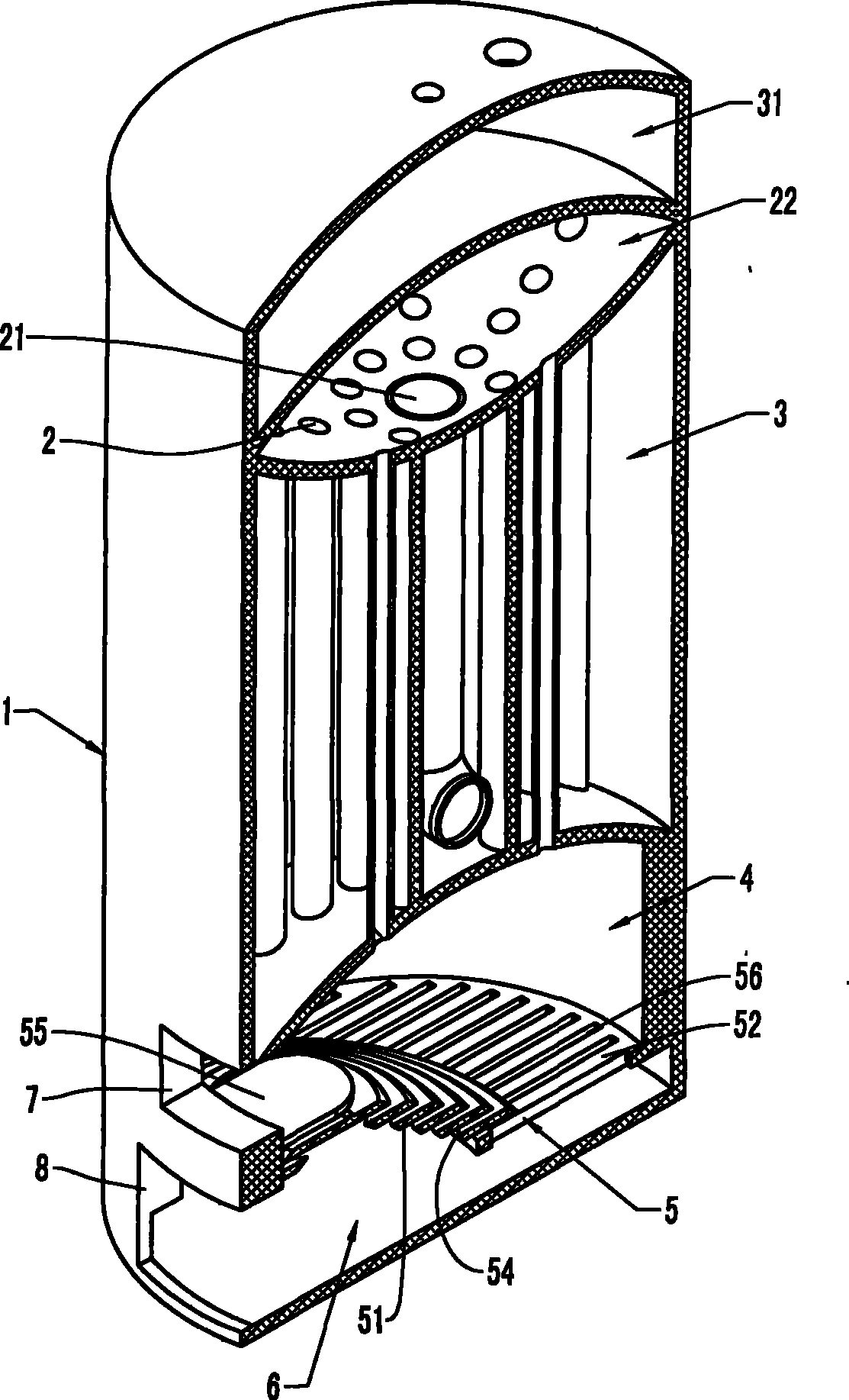
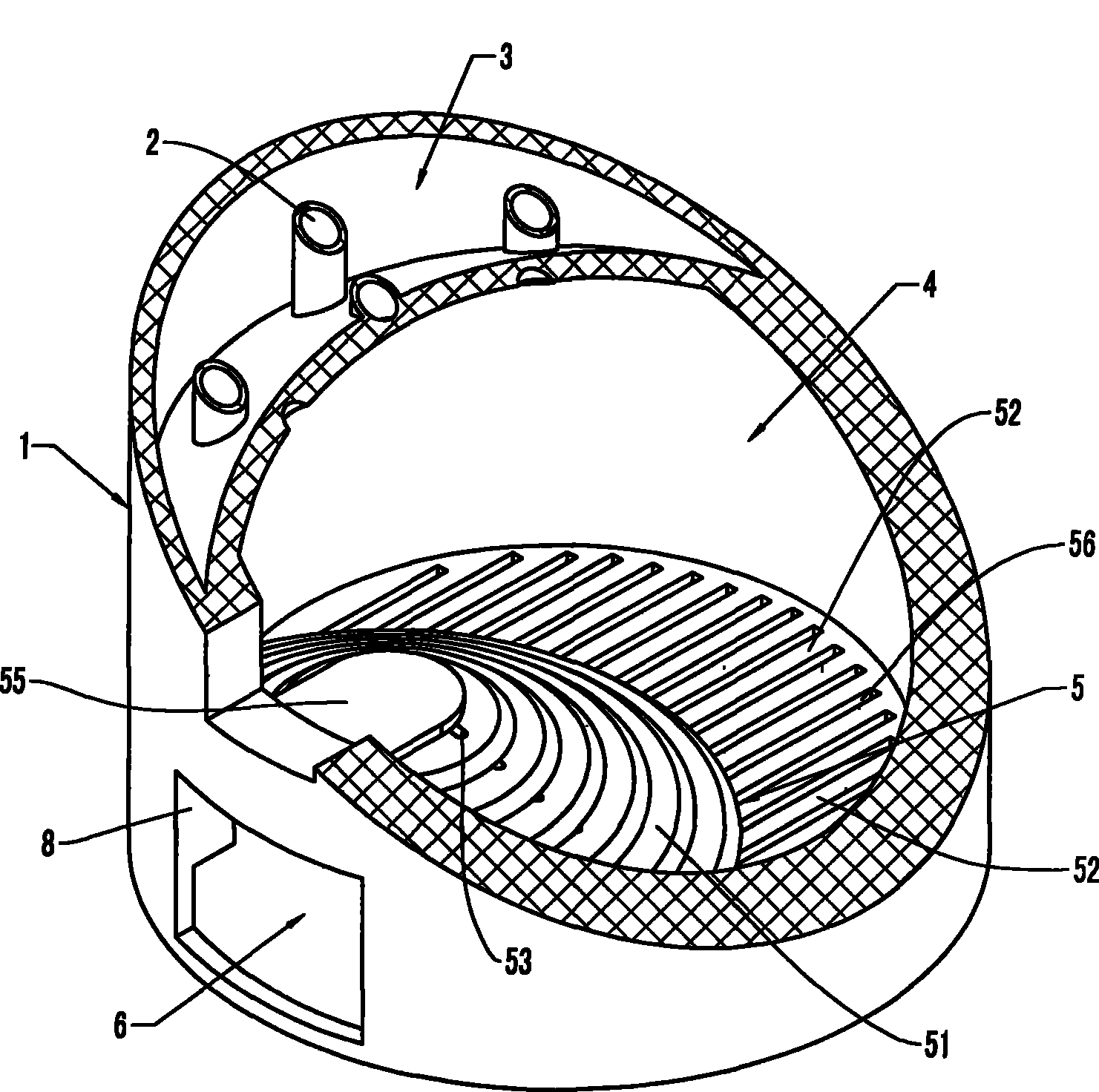
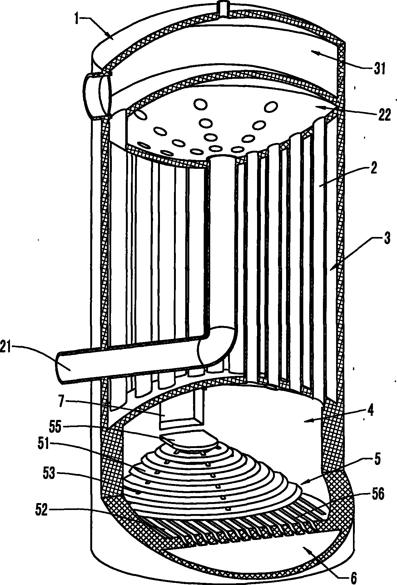
[0019] refer to figure 1 , figure 2 and image 3 , an energy-saving boiler, including a heat exchange chamber on the upper part of the furnace body 1 and a combustion furnace 4 on the lower part, the furnace 4 is provided with a furnace grate 5 and a slag chamber 6, and the furnace wall above the furnace grate 5 is provided with a furnace door 7 and The slag-clearing port, wherein the grate 5 in the furnace is divided into a conical part 51 and a flat surface 52, and the grate near the furnace door 7 is a conical part 51, starting from the furnace door 7 from high to low to the furnace Radiation extends to the plane part, that is, a layout with high outside and low inside is formed. The fuel is fed in from the furnace door 7, and can roll down along the cone-shaped part 51, and naturally spread out to the periphery.

[0020] The conical portion grate mentioned above can have two specific structures. One is that the conical portion grate has a stepped structure, which is sta...


PUM


Abstract

The invention relates to an energy-saving type boiler, comprising a heat exchange chamber arranged on the upper part of a boiler body and a furnace hearth arranged on the lower part of the boiler body, wherein the heat exchange chamber consists of a water-storing cavity, a smoke exhaust pipe and a main smoke pipe; the furnace hearth consists of a furnace gate, a furnace slag chamber, a furnace door and a clearing slag port; the furnace gate is divided into a pyramidal part and a plane part; the furnace gate close to one side of the furnace door is the pyramidal part which radially extends into a furnace hearth from the furnace door in descending order. The furnace gate is divided into a pyramidal feed zone and a plane zone, which can ensure that: the fuels are gradually heated and burned along the pyramidal zone, rolled to the plane zone for continuous burning and then discharged from the plane zone. The energy-saving type boiler has the characteristics of ingenious design, reasonablestructure and sufficient air supply as well as fuel burning; moreover, the long burning travel of fuels in the boiler ensures that the fuels are difficult to directly drop in the furnace slag chamberand discharge out, thereby saving energy and fuels. At the same time, as the energy-saving type boiler changes the direct discharging type into the backward-flow type for discharging smoke, the high-temperature fuel gas forms reheating, so as to ensure more sufficient heat exchange, larger gas producing quantity and quicker gas producing speed.

Description

Technical field: [0001] The invention belongs to the field of boilers, in particular to an energy-saving boiler with conical grates. Background technique: [0002] There are many types of existing boilers, and whether energy saving is considered two factors, one is sufficient combustion, and the other is heat exchange efficiency. At present, for coal-fired, wood-fired and other boilers that use solids as fuel, the furnace body is divided into upper and lower sections. and the slag cleaning port; the upper section is a heat exchange chamber, which is equipped with a smoke exhaust pipe and a water storage chamber, and the water storage chamber is equipped with necessary observation windows, pressure gauges, steam outlets, and water inlet and outlet valves. There are mainly two types of heat exchange methods, one is distributed in the furnace through the coil, the coil is connected with the upper water storage chamber, and the main smoke pipe passes through the water storage c...

Claims


Application Information

Patent Timeline
Patent Type & Authority Patents(China)
IPC IPC(8): F22B9/02F22B9/18F22B31/08F23H13/00
Inventor 黄传柳
Owner 黄传柳
Why Eureka
Try Eureka