
Two-stage flame generator

A generator and flame technology, applied in the burner, combustion ignition, combustion method, etc., can solve the problems of increasing the power adjustment range of the flame generator, and achieve the effects of significant energy saving, reduced consumption and simple structure

Active Publication Date: 2008-08-27
GUANGDONG HAIRONG ENVIRONMENTAL PROTECTION TECH CO LTD
View PDF0 Cites 14 Cited by
  • Summary
  • Abstract
  • Description
  • Claims
  • Application Information

AI Technical Summary

Problems solved by technology

[0003] The purpose of this invention is to provide a two-stage flame generator to solve the technical problem of increasing the power adjustment range of the flame generator without affecting the resistance of the pulverized coal burner, that is, the output of pulverized coal

Method used


Image

  • Two-stage flame generator
  • Two-stage flame generator
  • Two-stage flame generator

Examples


Embodiment Construction

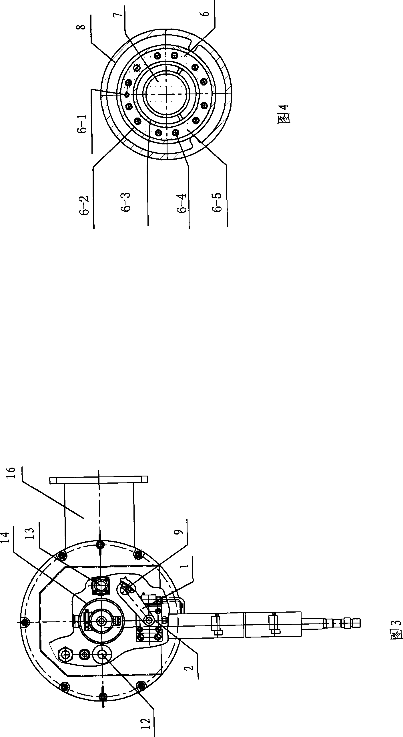
[0023] The structure of the novel flame generator of the present invention is shown in Figure 1, and it is mainly made up of following seven parts components and parts: 1, oil inlet pipeline; 2, vaporizer; ; 4. Air distribution device: including air distribution tube, preheating ring, heat insulation cover, etc.; 5. Detection mechanism: including fire viewing hole, visible light flame detection probe, etc.; , ignition gun and other pieces; seven, the second-stage flame generator. The shell is composed of rear hood, middle bellows and front air distribution tube. The first-stage flame generator is composed of an ignition gun, an oil inlet pipe and a vaporizer inside the shell. The second-stage flame generator is axially and concentrically set in the central ventilator of the first-stage flame generator.

[0024] In Fig. 1 and Fig. 2: 1, connecting plate, 2, cylinder, 3, hood, 4, bellows, 5, oil inlet pipe, 6, carburetor, 7, second-stage flame generator, 8, air distribution cy...


PUM


Abstract

The present invention discloses a double stage flame generator, comprising a housing, a first stage flame generator consisting of an ignition gun, an oil inlet tube and a carburetor, a second stage flame generator axially and concentrically sleeved inside a central ventilation chimney of the first stage flame generator. A vaporizer of the first stage flame generator is fixed inside an air distribution cylinder. The air distribution cylinder at the far end of the vaporizer is provided with a comparative long precombustion chamber. The axial center of the vaporizer of the first stage flame generator is provided with a guiding cylinder formed by circular holes. The guiding cylinder is used for placing the second stage flame generator, and is an air inlet path of part combustion promoting air. The second stage flame generator is positioned inside the guiding cylinder when the first stage flame generator is ignited, and stretches out to a coal powder combustor spout of the housing after the ignition. The flame generator has large power adjusting ratio, and is capable of realizing cooling furnace curve ignition. The temperature of flame is higher, and the rigidity of the flame is larger. The flame does not vie with the coal powder for air. The flame generator has further advantages of 100 percent gasification combustion, high combustion efficiency, low working pressure and large safety factor.

Description

technical field [0001] The invention relates to a fuel oil device-flame generator applied to coal-fired generator sets in thermal power plants of various sizes. Background technique [0002] Since all kinds of ignition devices currently used in power plant ignition in China, such as various oil guns, plasma generators, and high-frequency induction igniters, do not have a concentric axial two-stage structure, therefore, the traditional ignition device is used to directly start the cold furnace It is very difficult to ignite lean coal or anthracite with poor coal quality. Usually, a large oil gun must be put into operation to mix and burn. Otherwise, the burnout rate of coal is very low, which will pose a great threat to the safe operation of the boiler. When the pulverized coal burner of the boiler is ignited with a small oil gun, its cross-sectional size cannot be enlarged too much (otherwise it will affect its combustion characteristics), so that the output of the oil gun c...

Claims


Application Information

Patent Timeline
IPC IPC(8): F23Q13/00F23D11/00F23D11/44
Inventor 王雨蓬曹琴李本伟任志鹏李金光
Owner GUANGDONG HAIRONG ENVIRONMENTAL PROTECTION TECH CO LTD
Learn More