Dispersion type scintillation detector for impulse gamma detection

A scintillation detector and scattering technology, applied in the direction of instruments, measuring devices, scientific instruments, etc., can solve the problems of low sensitivity, large span of radiation field strength, and inability to measure pulsed gamma/X-rays accurately, so as to improve performance , Deduct the effect of interference

Inactive Publication Date: 2008-08-27
NORTHWEST INST OF NUCLEAR TECH +1
View PDF0 Cites 13 Cited by
  • Summary
  • Abstract
  • Description
  • Claims
  • Application Information

AI Technical Summary

Problems solved by technology

2. The pulsed gamma / X-ray energy spectrum cannot be accurately measured so far, and the intensity measurement requires the detection system to have a flat energy response; 3. The intensity span of the radiation field is large, and multiple detectors need to be used for joint measurement
Scintillator-based photodetectors are highly sensitive and suitable for the measurement of low-intensity gamma-ray beams, and their sensitivities are usually in the range of 10 -10 -10 -20 C.cm 2 , but because scintillators and optoelectronic devices are more sensitive to neutrons, even if inorganic scintillators are used, the γ / n resolution is difficult to exceed 20 times. At the same time, this type of detector is based on energy harvesting. The detection sensitivity of the detector varies drastically with the energy, and the energy response to gamma-ray intensity measurement is not ideal; the Compton detector is a charge-collecting detector, and its intrinsic γ / n resolution can reach more than 50 times, but the Very low, usually around 10 -19 -10 -23 C.cm 2 , suitable for the measurement of high-intensity gamma-ray beam parameters, its energy response is flatter than scintillation detectors, but not ideal

Method used


Image

  • Dispersion type scintillation detector for impulse gamma detection
  • Dispersion type scintillation detector for impulse gamma detection

Examples


Embodiment 1

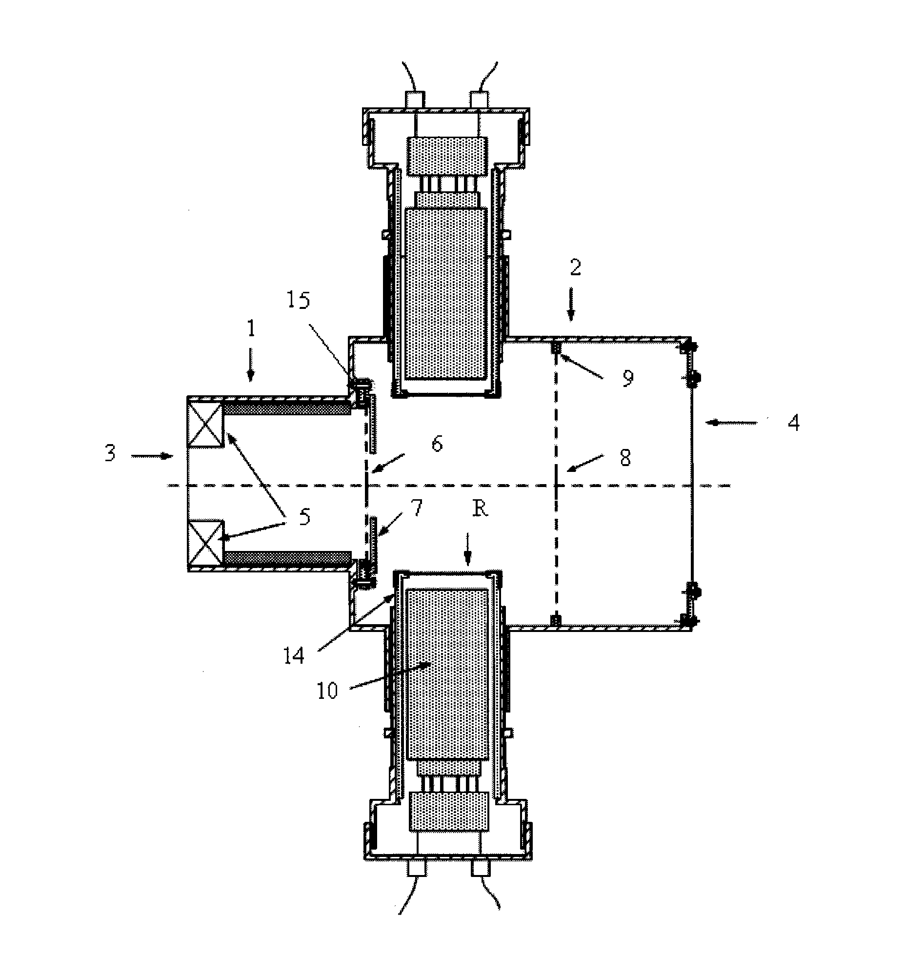
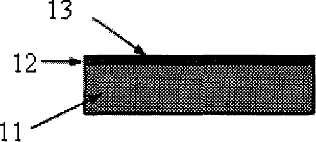
[0018] The distance between the front surface of the scintillator 11 and the central axis of the beam is 8 cm, the distance between the front target 6 and the center line of the scintillator 11 is 7 cm, and the distance between the rear target 8 and the center line of the scintillator 11 is 6 cm. The incident window 3 and the exit window 4 are 25 μm aluminum foils, which are used to seal the electrons in the space. The scintillator 11 is a ST401 plastic scintillator or a ZnO inorganic scintillator. The electronic filter 13 is 20 μm aluminum foil. The electronic aluminum retaining ring 7 is a 3mm thick aluminum sheet, and the middle expansion hole of the electronic aluminum retaining ring 7 is 50mm, and the distance between the cleaning magnet 5 and the front target 6 is 80mm. The front target 6 and the rear target 8 are Tungsten sheets of 20×0.1 mm are suspended on the front target frame 15 and the rear target frame 9 with thin wires, and the front target frame 15 and the...

Embodiment 2

[0022] In this embodiment, the distance between the front surface of the scintillator 11 and the central axis of the beam is 5 cm, the distance between the front target 6 and the center line of the scintillator 11 is 5 cm, and the distance between the rear target 8 and the center line of the scintillator 11 is 4 cm. The incident window 3 and the exit window 4 are 20 μm aluminum foil. The scintillator 11 is a ST401 plastic scintillator or a ZnO inorganic scintillator. The electronic filter 13 is 10 μm aluminum foil. The electronic aluminum retaining ring 7 is a 2mm thick aluminum sheet, and the middle expansion hole of the electronic aluminum retaining ring 7 is 40mm, the distance between the cleaning magnet 5 and the front target 6 is 60mm. The front target 6 and the rear target 8 are Tungsten sheets of 20×0.1 mm are suspended on the front target frame 15 and the rear target frame 9 with thin wires, and the front target frame 15 and the rear target frame 9 are frame struc...

Embodiment 3

[0024] In this embodiment, the distance between the front surface of the scintillator 11 and the central axis of the beam is 10 cm, the distance between the front target 6 and the center line of the scintillator 11 is 10 cm, and the distance between the rear target 8 and the center line of the scintillator 11 is 8 cm. The incident window 3 and the exit window 4 are 30 μm aluminum foil. The scintillator 11 is a ST401 plastic scintillator or a ZnO inorganic scintillator. The electronic filter 13 is 30 μm aluminum foil. The electronic aluminum retaining ring 7 is a 4mm thick aluminum sheet, and the middle expansion hole of the electronic aluminum retaining ring 7 is 60mm, and the distance between the cleaning magnet 5 and the front target 6 is 100mm. The front target 6 and the rear target 8 are Tungsten sheets of 20×0.1mm are suspended on the front target frame 7 and the rear target frame 9 with thin metal wires, and the front target frame 7 and the rear target frame 9 are f...


PUM


Abstract

The invention belongs to a radiator detecting device, in particular relating to a scattering-type scintillation detector for pulse and gamma-ray detection. An upper photoelectric device and a lower photoelectric device in the scintillation detector are respectively provided with the same electron filter, reflecting film, scintillation unit and photomultiplier which are arranged in symmetry. Therefore, the sensitivity difference between two detectors at both sides can be pre-set with the photoelectric device at one side as a background photoelectric device and the photoelectric device at the other side as a main signal detector. During measurement, a 3 millimeters thick granite sheet or aluminum sheet is added in front of the scintillation unit of the photoelectric device at one side to block electrons exiting out of a target so that the electrons are impossible to reach the scintillation unit, thus only surrounding gamma-ray and disturbance signals of neutrons are obtained. After time delay rectification and sensitivity rectification, the output signals of the two photoelectric devices are mutually deducted to obtain the true signals. Therefore, the scattering-type scintillation detector for pulse and gamma-ray detection can effectively deduct the disturbance caused by deficiency in shielding so as to improve the performance of detectors.

Description

technical field [0001] The invention belongs to a radiation detection device, in particular to a scattering scintillation detector for pulse gamma detection. Background technique [0002] Pulsed radiation field gamma ray diagnosis has the following three characteristics: 1. The radiation field is usually a mixed radiation field of pulsed neutrons and gamma rays, and the neutron intensity is sometimes several times higher than that of gamma rays, so the detector system is required to have Very high γ / n resolving power. 2. The pulsed gamma / X-ray energy spectrum cannot be accurately measured so far, and the intensity measurement requires the detection system to have a flat energy response; 3. The intensity span of the radiation field is large, and multiple detectors need to be used for joint measurement. [0003] In the existing pulsed gamma (γ) ray detection, two types of detector systems are mainly used: one is a scintillation detector composed of photoelectric devices such ...

Claims


Application Information

Patent Timeline
Patent Type & Authority Applications(China)
IPC IPC(8): G01T1/20G01T1/203
Inventor 欧阳晓平夏良斌王群书
Owner NORTHWEST INST OF NUCLEAR TECH
Why Eureka
Try Eureka