
Plate shell-type nonsaturated evaporation condensing plant

An evaporative condensation, plate-and-shell technology, used in evaporators/condensers, lighting and heating equipment, steam/steam condensers, etc., can solve the problem of weakened water spiral flow, poor heat transfer effect, and affected heat transfer effect. and other problems, to achieve the effect of increasing the sedimentation velocity, increasing the effective heat transfer area, and enhancing the cooling effect.

Inactive Publication Date: 2008-09-03
SOUTH CHINA UNIV OF TECH
View PDF0 Cites 25 Cited by
  • Summary
  • Abstract
  • Description
  • Claims
  • Application Information

AI Technical Summary

Problems solved by technology

Compared with the non-evaporative cooling device, there is no ventilation in the tube of the vertical condenser, and only the sensible heat of the temperature rise of the water is used to take away the heat. Not only is the heat exchange efficiency not high, but the cooling water needs to be treated with a cooling tower to be recycled, resulting in The overall heat exchange effect is not good, the structure is complex, and the operating cost is high; in addition, the cooling water of the vertical condenser is distributed to each heat exchange tube through a water separator with a chute, and forms a spiral water flow along the inner wall of the heat transfer tube. Flowing down, as the drop height increases, the spiral flow of water weakens, which will greatly affect the heat transfer effect

Method used


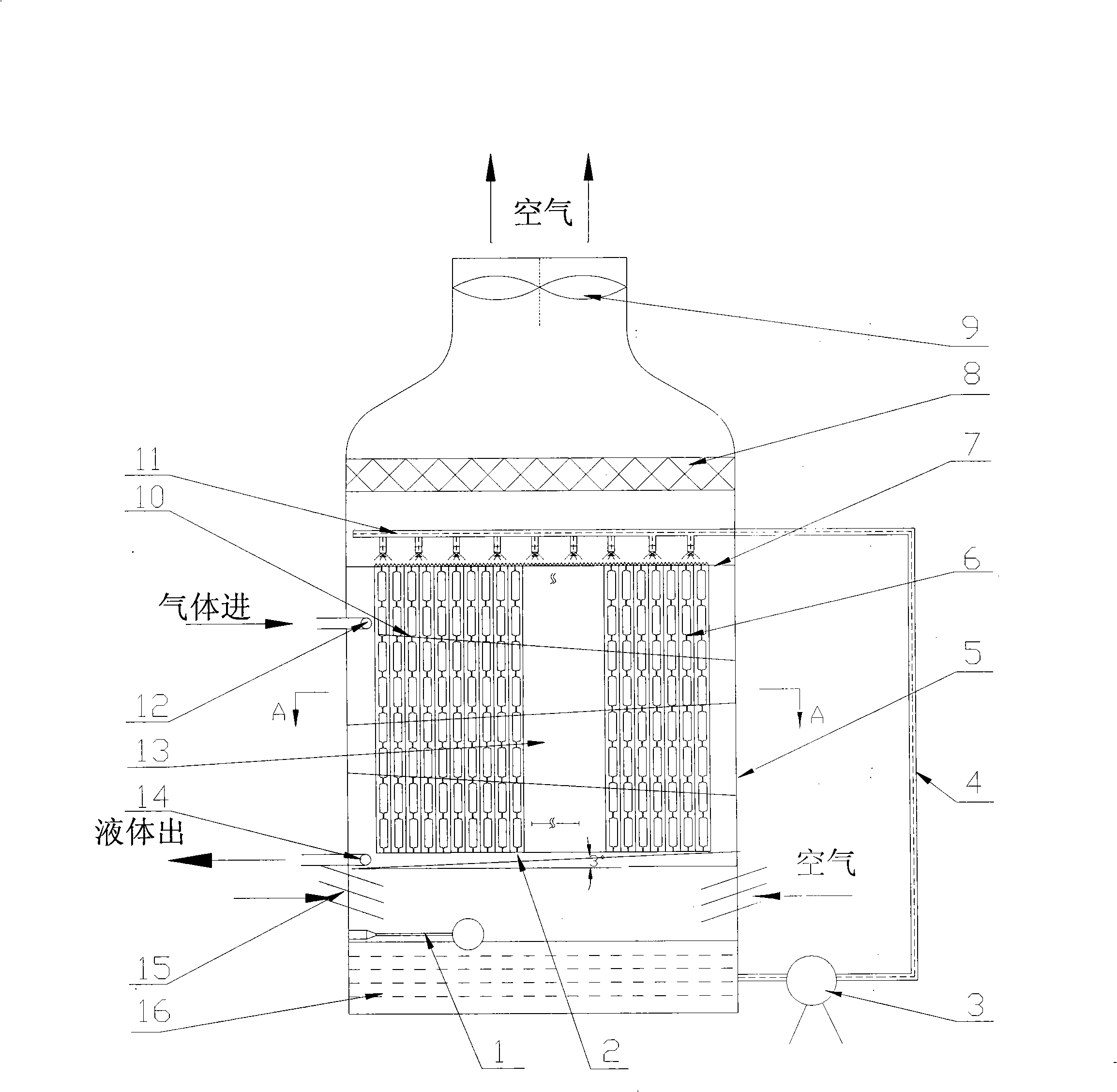
Image

  • Plate shell-type nonsaturated evaporation condensing plant
  • Plate shell-type nonsaturated evaporation condensing plant
  • Plate shell-type nonsaturated evaporation condensing plant

Examples


Embodiment Construction

[0016] The present invention will be further described below in conjunction with the accompanying drawings, but the present invention is not limited thereto.

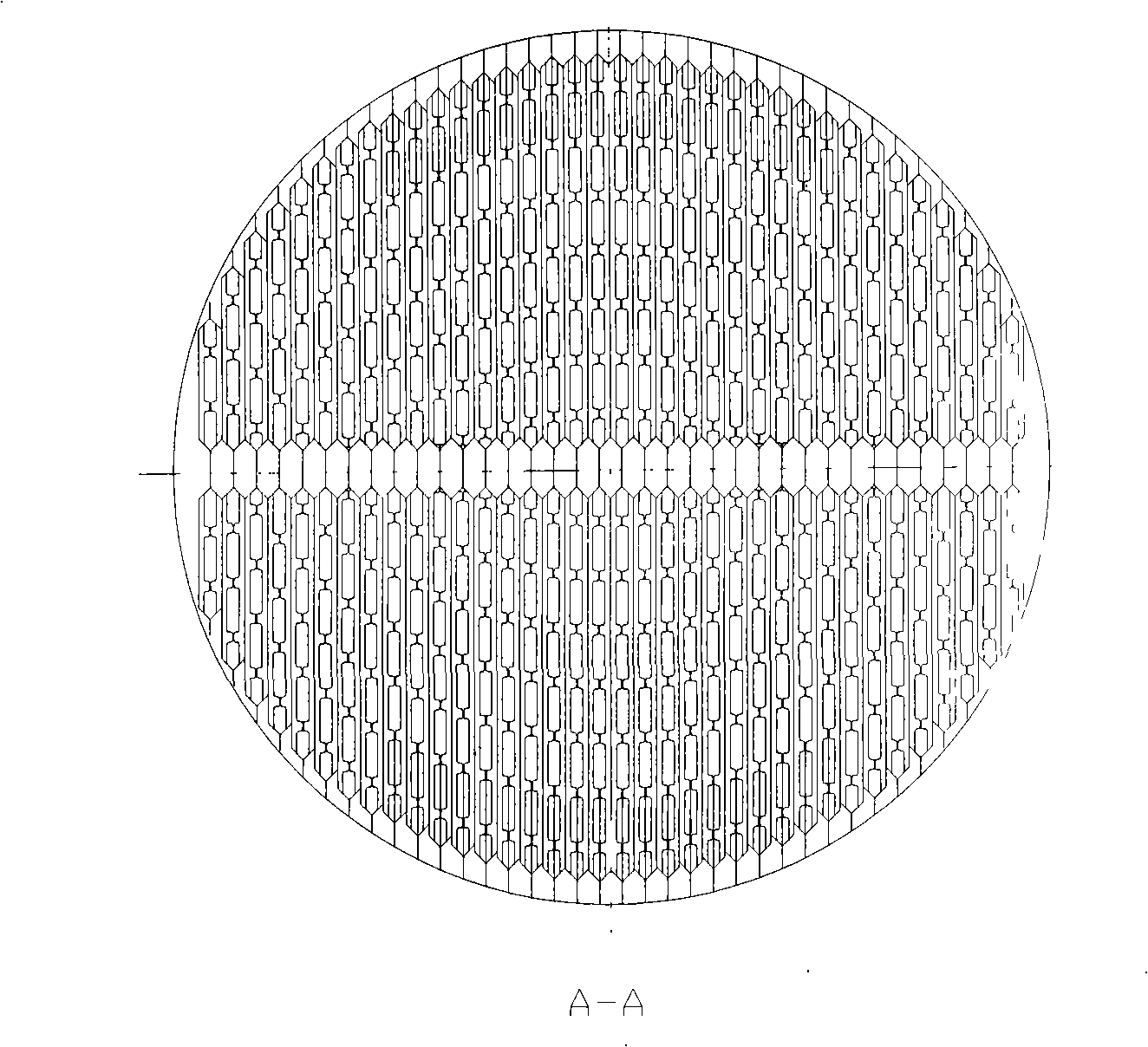
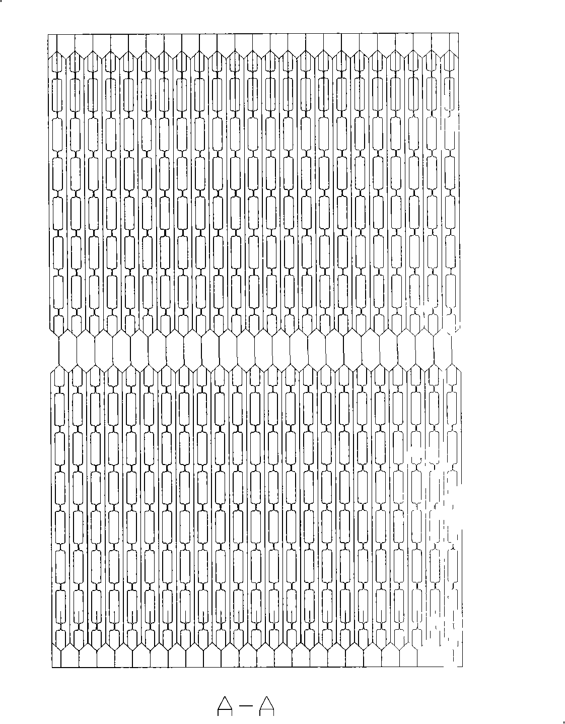
[0017] Such as figure 1 As shown, the plate-shell unsaturated evaporative-condensing equipment of the present invention includes an upper box, a lower box and a plate-shell heat exchanger 13 . The upper box contains an axial flow fan 9, a water baffle 8, and a top water collector 11 to realize the air circulation and water distribution of the cooling equipment; the lower box contains an air inlet grid 15, a float valve 1 and a bottom water collection tank 16. The air intake grid 15 is cylindrical and located on the upper part of the lower box, allowing air to enter the lower box from any direction; the top water collector 11 is connected to the bottom water collection tank 15 by the water pump 3 through the circulating water pipeline 4. The plate-shell heat exchanger 13 is fixedly connected with the upper box body and ...


PUM


Abstract

The invention discloses a plate-shell type nonsaturated evaporation condensing device comprising an upper housing body, a plate-shell type heat exchanger, and a lower housing body. The upper housing body is connected with the lower housing body by a water pump, and the heat exchange main body is the plate-shell type heat exchanger which is connected with the upper housing body and the lower housing body respectively. The plate-shell type heat exchanger comprises an upper tube plate, a lower tube plate, heat exchange plate bundles, a housing, a baffle, a gas-distributing pipe and a collector tube. The upper tube plate is provided horizontally, the lower tube plate declines in the direction of the flowing hot fluid, the plate type heat exchanger gets through holes in the upper tube plate and the lower tube plate with a in-line modus, and the baffle is disposed among the heat exchange plate bundles. The inventive device is provided with a large effective heat transfer area, even aqueous film allocation, rapid settling velocity, quick transfer of nonsaturated evaporation heat and moisture, anabatic liquid membrane fluctuation, enhanced turbulent flow, an attenuated liquid membrane laminar sublayer, decreased heat resistance, a small condensing resisting force and a remarkable condensing effect. Deposit and erosion are reduced, a mall floor space is provided, and the inventive device is suitable for condensing and cooling field.

Description

technical field [0001] The present invention relates to an evaporating and condensing equipment, more specifically, it relates to a plate-shell type unsaturated evaporating and condensing equipment Background technique [0002] The refrigerant condenses and releases heat in the tubes of traditional non-evaporative cooling equipment. The water outside the tubes sprays down from the top of the tube bundle, forming a layer of water film on the surface of the tubes, and then drips to the next layer of tube rows; the wind blows from the bottom of the tube bundle. It passes through the tube bundle and conducts heat and mass transfer with the water film on the tube surface to form unsaturated evaporation. Unsaturated evaporation mainly occurs at the contact interface between the water film on the surface of the heat transfer tube wall and the air. This process is a discontinuous falling film process. It is difficult for the water film to cover the tube surface completely and unifor...

Claims


Application Information

Patent Timeline
Patent Type & Authority Applications(China)
IPC IPC(8): F25B39/04F25B19/00F28B1/02F28B5/00
Inventor 朱冬生李元希郭常青吴治将
Owner SOUTH CHINA UNIV OF TECH
Learn More