
Reading circuit of micro-array biosensor

A biosensor and readout circuit technology, applied in the field of microarray biosensors, can solve the problems of high hazards, etc., and achieve the effects of low power consumption, fewer transistors, and simple circuit structure

Inactive Publication Date: 2008-09-03
CHONGQING UNIV
View PDF0 Cites 12 Cited by
  • Summary
  • Abstract
  • Description
  • Claims
  • Application Information

AI Technical Summary

Problems solved by technology

Since the readout circuit of the current microarray biosensor basically does not involve noise suppression, the most important noise sources in the readout circuit include 1 / f noise (flicker noise of MOS transistor), KTC noise (reset noise ) and microarray fixed-bias noise signals, these unsuppressed or weakened noise signals V noise (noise signal V noise The sum of all noises in the table) is output to the subsequent circuit along with the readout circuit
Since the front-stage noise signal may be amplified and transmitted to the subsequent stage circuit, the harm is often greater. In order to improve the signal-to-noise ratio of the output signal, it must be eliminated or weakened.

Method used


Image

  • Reading circuit of micro-array biosensor
  • Reading circuit of micro-array biosensor
  • Reading circuit of micro-array biosensor

Examples


Embodiment Construction

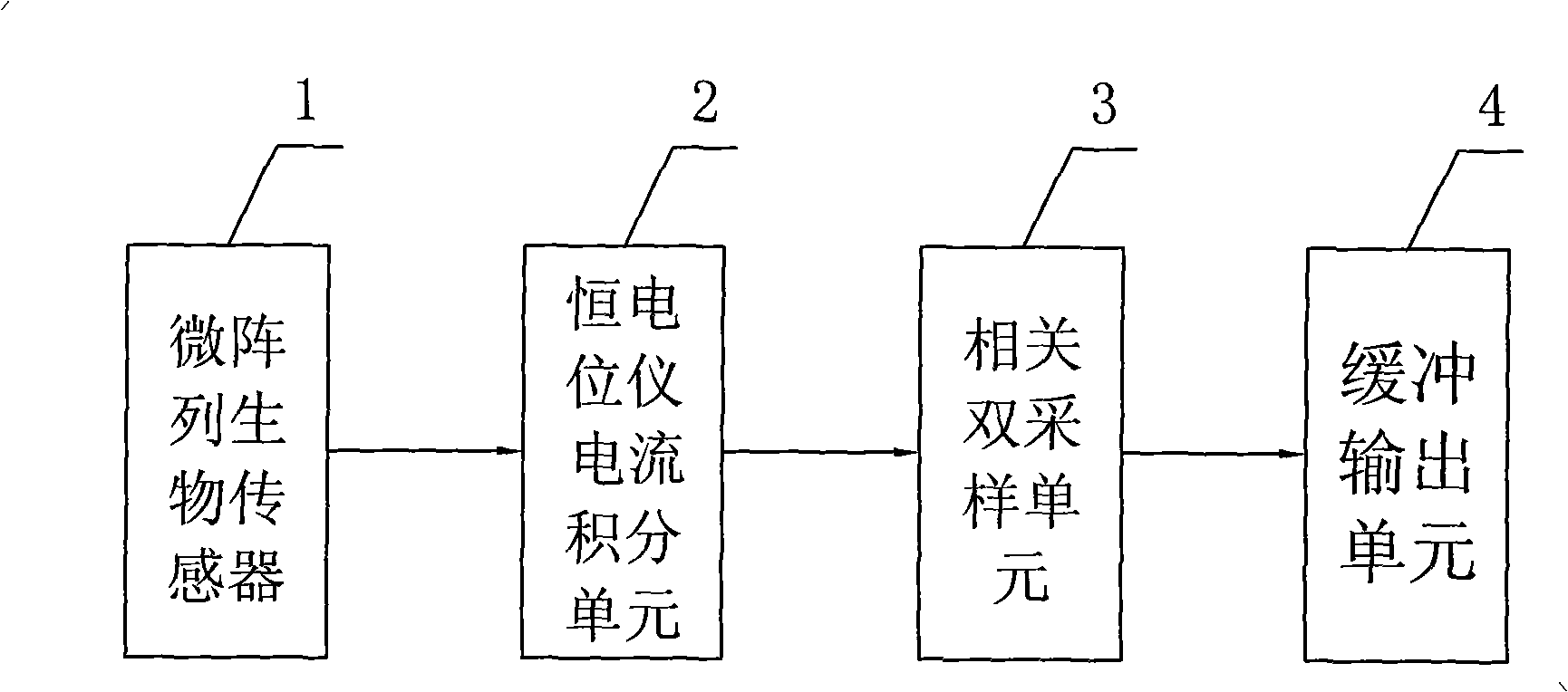
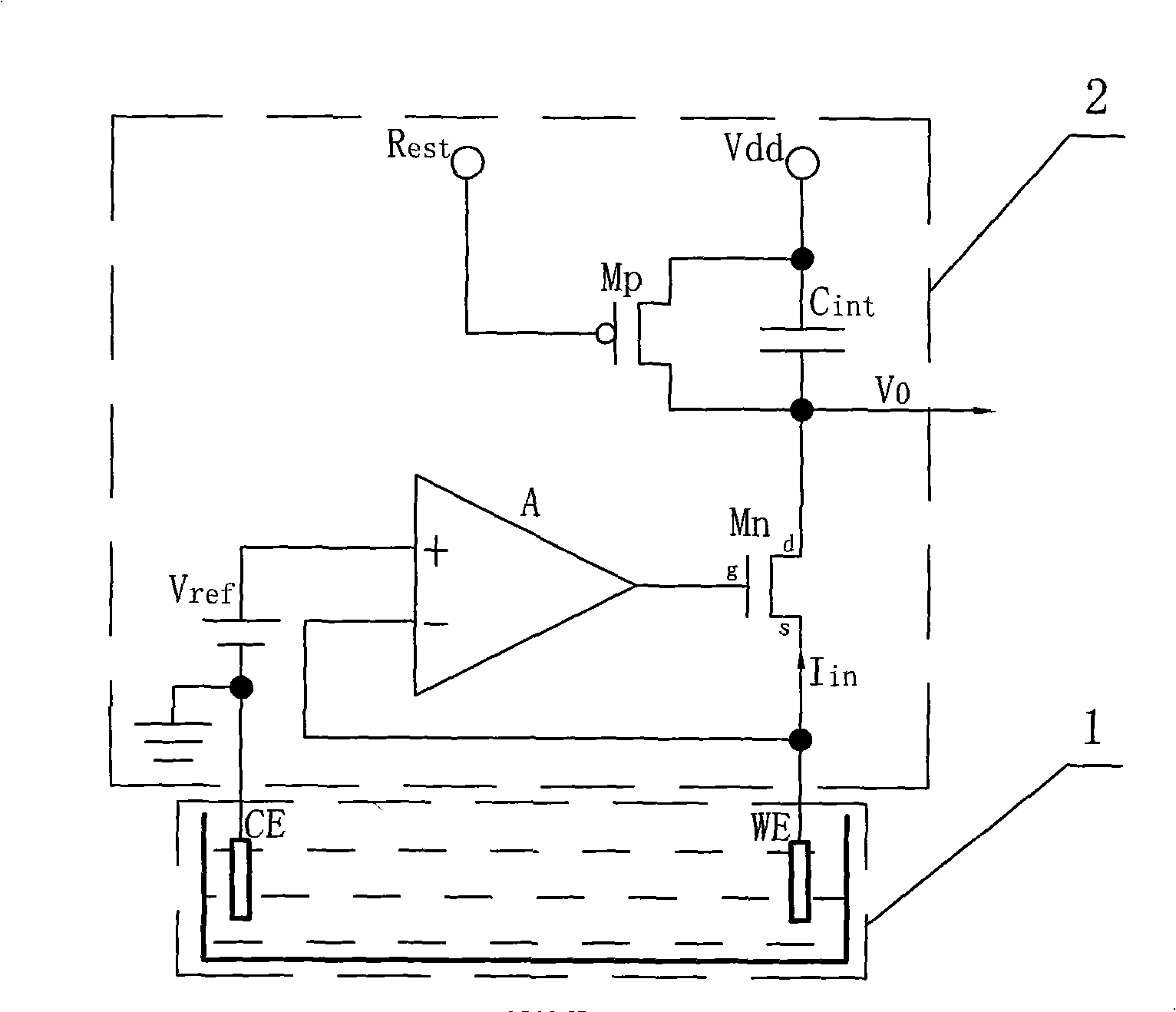
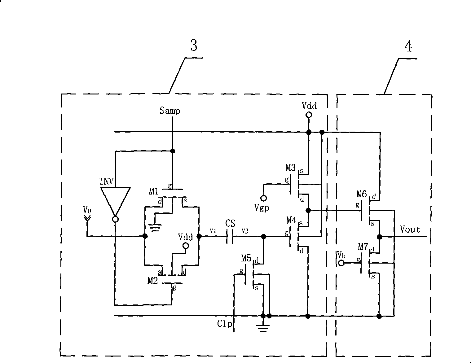
[0016] refer to figure 1 , the readout circuit of the microarray biosensor of the present invention, the output end of the microarray biosensor 1 is connected to a potentiostat current integration unit 2, and the potentiostat current integration unit is between the working electrode and the counter electrode of the microarray biosensor Provide a constant bias voltage, and convert the current signal from the microarray biosensor into a voltage signal output. The correlation double sampling unit 3 between the potentiostat current integration unit 2 and the buffer output unit 4, the correlation double sampling unit samples the voltage signal output by the potentiostat current integration unit and outputs it to the buffer output unit after denoising processing.

[0017] refer to figure 1 and figure 2 , The potentiostat current integration unit 2 includes a potentiostat and an integrator electrically connected to the potentiostat. The potentiostat current integration unit provi...


PUM


Abstract

The invention discloses a playback circuit of a micro-array biologic sensor, which includes a buffered output unit, and a current integration unit which is connected with the output terminal of the micro-array biologic sensor and provides a constant bias voltage between the working electrode and the counter electrode of the micro-array biologic sensor, and transforms the current signal from the micro-array biologic sensor into the voltage signal; and a correlated double sampling unit which is connected between the potentiostat current integration unit and the buffered output unit, the voltage signal outputted from the correlated double sampling unit sampling potentiostat current integration unit is denoised and outputted to the buffered output unit. The invention can eliminate the noise signal in the biological microelectrode sensor output signal, and improves the signal-noise ratio of the biological microelectrode sensor output signal.

Description

technical field [0001] The invention relates to a microarray biosensor, in particular to a readout circuit of the microarray biosensor. Background technique [0002] An electrochemical biosensor is a biosensor with an electrochemical signal converter, which is generally considered to be a chemically modified electrode. Electrochemical electrodes are composed of conductive, semiconductor or ion-conductive materials as signal converters, coated with a layer of biochemical or biological film as sensitive elements, and finally the electrical signal is used as a characteristic detection signal. According to the different measurement methods of electrical signals, it can generally be divided into three types: current type, potential type and conductivity type, and current type and potential type are dominant. Due to the shortcomings of traditional chemically modified electrodes such as large volume, low sensitivity, and high noise, chemically modified electrodes for biosensors ar...

Claims


Application Information

Patent Timeline
Patent Type & Authority Applications(China)
IPC IPC(8): G01N27/416
Inventor 潘银松孔谋夫刘嘉敏李向全张仁富
Owner CHONGQING UNIV
Learn More