Asymmetry parallel excitation type bistable state permanent magnet control mechanism

A permanent magnet operation and bistable technology, which is applied in the direction of protection switch operation/release mechanism, power device inside the switch, high-voltage air circuit breaker, etc., can solve the problem of affecting the cost of the controller, affecting the working performance of the electromagnetic operating mechanism, Affect the reliability of the controller and other issues to achieve the effect of shortening the trigger time, good retention characteristics and dynamic performance, and overcoming the slow opening speed

Inactive Publication Date: 2008-09-03
SHANGHAI RENMIN ELECTRICAL APP WORKS
View PDF0 Cites 2 Cited by
  • Summary
  • Abstract
  • Description
  • Claims
  • Application Information

AI Technical Summary

Problems solved by technology

[0003] At present, the common problem of permanent magnet mechanism is: when the opening and closing electromagnetic operation, it is necessary to supply a large DC excitation current to the excitation coil
A large DC impulse current puts high performance requirements on the electronic control device, which not only affects the cost of the controller, but more seriously affects the reliability of the controller, thus affecting the working performance of the electromagnetic operating mechanism

Method used


Image

  • Asymmetry parallel excitation type bistable state permanent magnet control mechanism
  • Asymmetry parallel excitation type bistable state permanent magnet control mechanism

Examples


Embodiment Construction

[0016] The present invention will be further described below in conjunction with the accompanying drawings and specific embodiments.

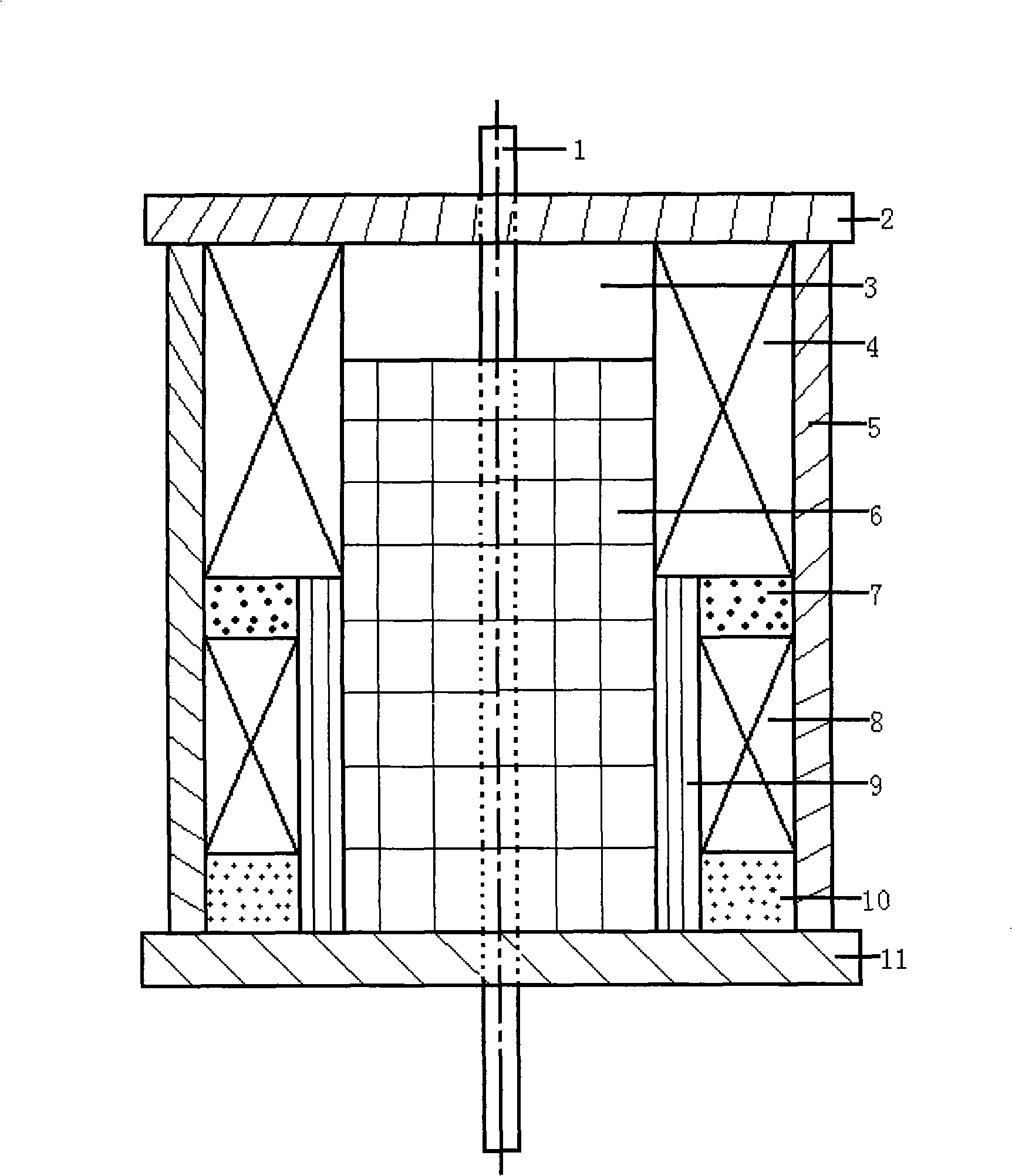
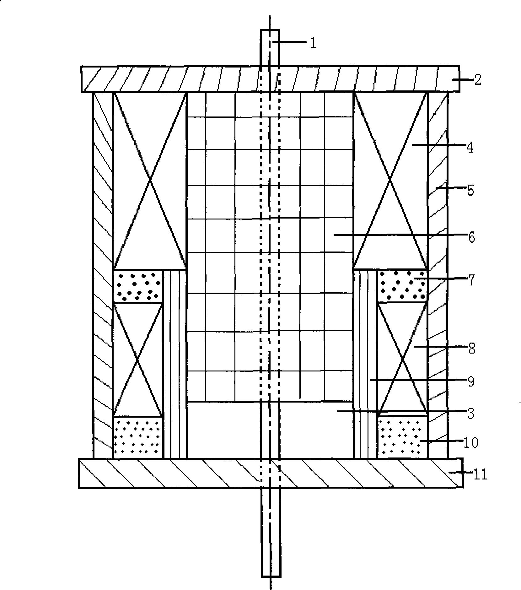
[0017] see figure 1 , an asymmetric parallel-excited bistable permanent magnet operating mechanism, including a moving iron core 6, a permanent magnet 9, an opening coil 4, a closing coil 8, a first static iron core 7, a second static iron core 10, an opening End cover 2, closing end cover 11, outer yoke 5, output rod 1. The outer yoke 5 is a hollow cylinder, and the outer yoke 5 is fixed and clamped by the opening end cover 2 and the closing end cover 11 through nuts. The moving iron core 6 is placed in the center of the outer yoke 5 of the hollow cylinder, and the center of the moving iron core 6 is fixed with a Output rod 1.

[0018] The static iron core is composed of the first static iron core 7 and the second static iron core 10. Between the hollow cylindrical yoke 5 and the moving iron core 6, the opening coil 4, the second opening coi...


PUM


Abstract

The present invention relates to a permanent magnet control mechanism for middle and high-pressure switch device. An anti-symmetric shunt excitation type bistable permanent magnet control mechanism, whose outer magnet yoke is a hollow cylinder, the outer magnet yoke is clipped by an end cap of an off-breaker and an end cap of a on- breaker, the moving iron-core is arranged at the center of the cylindrical magnet yoke, the moving iron-core center is fixed with a capability lever; the static iron-core is consist of first static iron-core and second static iron-core, the division brake coil, the first static iron-core, the on-brake coil, the second static iron-core and the permanent magnet are installed in sequence between the static iron-core and the moving iron-core from the division brake end cap to the on-brake end cap between the hollow cylinder magnet yoke and the moving iron-core, and the permanent magnet is placed at the first static iron-core, the on-brake coil and inside of the second static iron-core. The present invention with good output characteristic can improve division brake velocity effectively, and reduce the exciting current of on-off brake, and reduce the touching time of the moving iron-core, and overcomes the defect such as the slow on-off brake velocity of the existing mechanism, big power consumption etc, and is good for miniaturization of the mechanism.

Description

technical field [0001] The invention relates to power supply and distribution technology of electric power system, in particular to a permanent magnet operating mechanism for medium and high voltage switchgear. Background technique [0002] As electrical components for controlling and distributing electric energy, medium and high voltage switchgears can seriously affect the safety and quality of power supply of the power system. The main function of the switchgear is reflected in the operation of closing and opening the contacts, and the closing and opening of the contacts is realized by the operating mechanism. Therefore, the reliability of the operating mechanism becomes the main responsibility for the reliability of the switchgear. The development of the operating mechanism has gone through several stages of hydraulic mechanism, electromagnetic mechanism and spring mechanism. After a long-term operation test, it is known that these mechanisms have a high failure probabi...

Claims


Application Information

Patent Timeline
Patent Type & Authority Applications(China)
IPC IPC(8): H01H71/32H01H33/38H01H3/28
Inventor 谭东现牟坚
Owner SHANGHAI RENMIN ELECTRICAL APP WORKS
Why Eureka
Try Eureka