
Deconvolution interweave machine and method realized based on FPGA

A deconvolution and interleaver technology, applied in the field of deconvolution and interleaving, can solve the problems of high power consumption, low storage space usage efficiency, idle storage units, etc., and achieve the goal of increasing working speed, improving usage efficiency, and high application value Effect

Inactive Publication Date: 2008-09-03
SHENZHEN COSHIP ELECTRONICS CO LTD
View PDF0 Cites 21 Cited by
  • Summary
  • Abstract
  • Description
  • Claims
  • Application Information

AI Technical Summary

Problems solved by technology

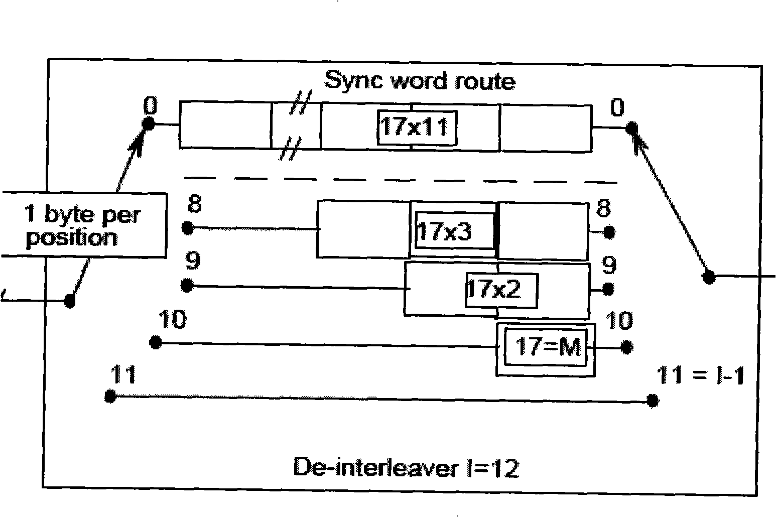
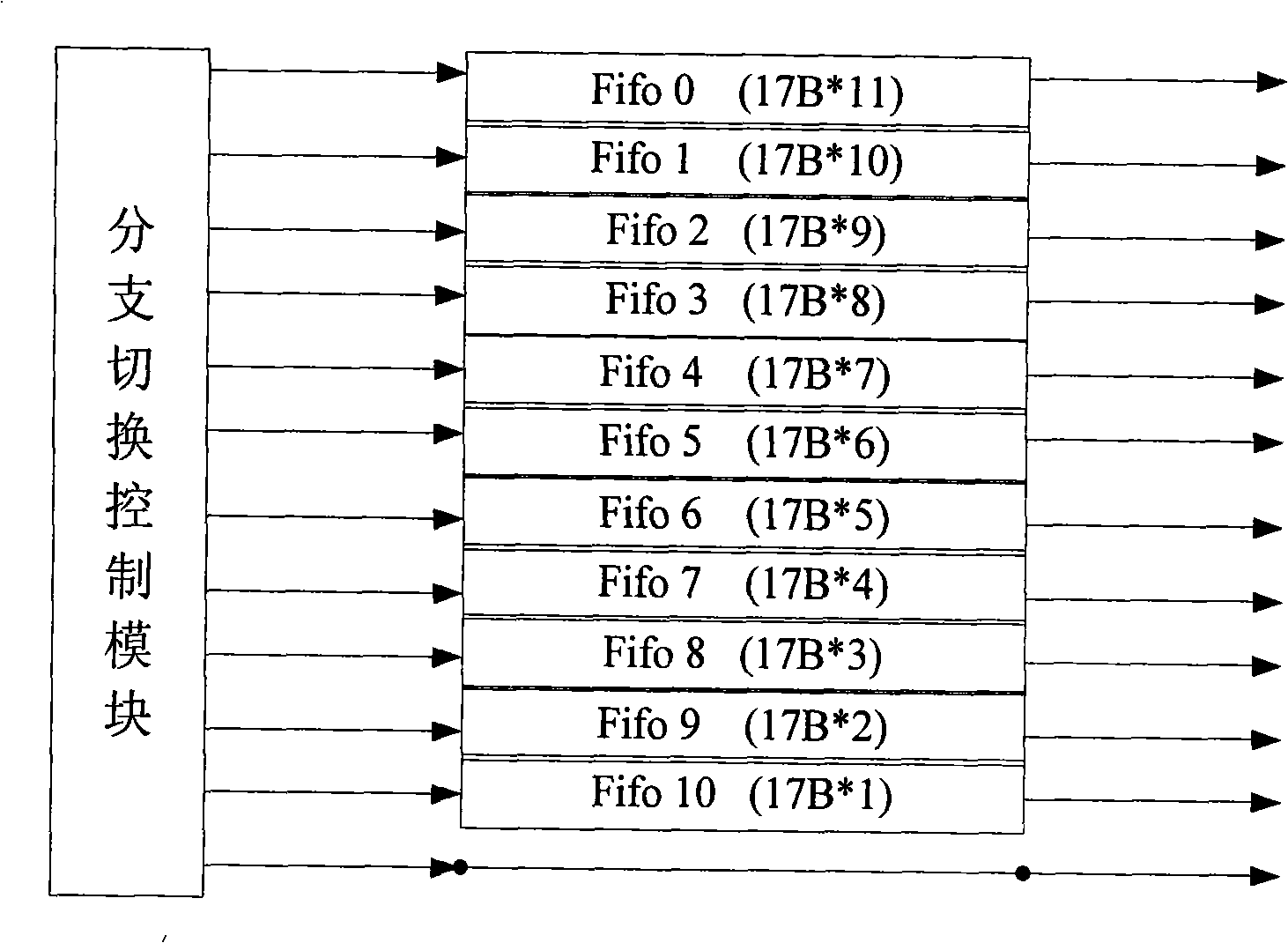
[0007] 1. When implemented in an FPGA (Field Programmable Gate Array, Field Programmable Gate Array) logic device, since the FPGA only supports storage memory blocks (registers) with a power-of-two depth, if FIFO is used to implement each branch storage unit, Then the FIFO storage space required by each branch is 256, 256, 256, 256, 128, 128, 128, 128, 64, 64, 32 and 0 bytes in sequence, occupying a total of 1696 bytes of storage space. Therefore, the actual use of The storage space is 1122 bytes, and the utilization efficiency of the storage space is: 1122 / 1696=66%, so the utilization efficiency of the storage space is low
[0008] 2. The aforementioned design consumes a lot of power due to the frequent switching of branch switches
[0011] At the same time, since the FPGA only supports storage memory blocks (registers) with a power-of-two depth, although the interleaver only needs 1122*8bits, it must be implemented with a power-of-two storage space, so a dual-port RAM is used 11-bit address lines are required, and the storage space is 2048*8bits
[0012] The disadvantage of this solution is that the area occupied by the register is increased; at the same time, many storage units are left idle, and the utilization efficiency of the storage space is 1122 / 2048=55%, which has the disadvantage that the utilization efficiency of the storage space is low

Method used


Image

  • Deconvolution interweave machine and method realized based on FPGA
  • Deconvolution interweave machine and method realized based on FPGA
  • Deconvolution interweave machine and method realized based on FPGA

Examples


Embodiment Construction

[0041] Please refer to Figure 4 As shown, it is a schematic structural diagram of a specific embodiment of the deconvolution interleaver implemented based on FPGA in the present invention. This embodiment is a simulation implementation figure 1 The deconvolutional interleaver shown. The deconvolution interleaver in this embodiment includes: two read-write address generators 11 and 12 , dual-port RAMs 21 and 22 with 1024*8 and 256*8 respectively, and a controller 30 .

[0042] Since the FPGA only supports storage memory blocks (registers) with a power-of-two depth, although the interleaver only needs 1122*8 bits, it must be implemented with a power-of-two register. Therefore, in the deconvolution interleaver of the present embodiment: the dual-port RAM 21 of 1024*8 bits is an analog figure 1 The shift register of branches 0 to 6 shown; the dual-port RAM 22 of 256*8bits is analog figure 1Branches 7 to 11 of the shift register are shown. The part of the output (Out) has a s...


PUM


Abstract

The invention discloses a deconvolution interleaver based on FPGA and a deconvolution interleaving method. The deconvolution interleaver comprises two dual-port RAMs, two read-write address generators, and a controller, wherein the dual-port RAM has the memory deepness of power of 2,and each of the dual-port RAMs is used in a plurality of shift registers with continuous branch; each of the read-write address generators is connected with a dual-port RAM; the controller is respectively connected with the dual-port RAMs and the read-write address generators, outputs a selecting and controlling signal, and selects one of the read-write address generators to produce the output of read address and write address. The controller also outputs a selecting signal to select the dual-port RAM corresponding to the read address and write address, writes the input data in the memory space corresponding to the read address in the dual-port RAM, or reads and outputs the data in the memory space corresponding to the read address in the dual-port RAM. The invention has the characters of high utility rate of memory space and fast working speed.

Description

technical field [0001] The invention relates to deconvolution interleaving technology, in particular to a deconvolution interleaver and deconvolution interleaving method realized based on FPGA. Background technique [0002] In communication systems, the general role of channel coding is to correct random errors that occur in the channel. However, channel error correction coding often needs to be combined with data interleaving technology in practical applications. This is because most channel errors are sudden, that is, when an error occurs, it often has a strong correlation, and even a continuous piece of data is wrong. At the same time, due to the concentration of errors, the error correction capability of the error correction code may be exceeded, so a data interleaver is added at the sending end, and a deinterleaver is added at the receiving end to disperse the burst errors of the channel to facilitate error correction. Here, adding an interleaver and a deinterleaver to...

Claims


Application Information

Patent Timeline
IPC IPC(8): H03M13/23H03M13/27
Inventor 郭树印
Owner SHENZHEN COSHIP ELECTRONICS CO LTD
Learn More