ROF base station uplink of wavelength-division multiplex passive optical network and its system

A passive optical network and wavelength division multiplexing technology, applied in the field of optical communication, can solve the problems of increasing the complexity of base stations, and achieve the effects of saving system costs, reducing occupation, and reducing impact

Inactive Publication Date: 2008-09-03
PEKING UNIV
View PDF1 Cites 17 Cited by
  • Summary
  • Abstract
  • Description
  • Claims
  • Application Information

AI Technical Summary

Problems solved by technology

But the problem is also obvious, that is, the radio frequency (RF) signal needs to be down-converted at the base station, so that each base station needs a high-frequency millimeter-wave source and a millimeter-wave mixer, which greatly increases the complexity of the base station

Method used


Image

  • ROF base station uplink of wavelength-division multiplex passive optical network and its system
  • ROF base station uplink of wavelength-division multiplex passive optical network and its system
  • ROF base station uplink of wavelength-division multiplex passive optical network and its system

Examples


Embodiment 1

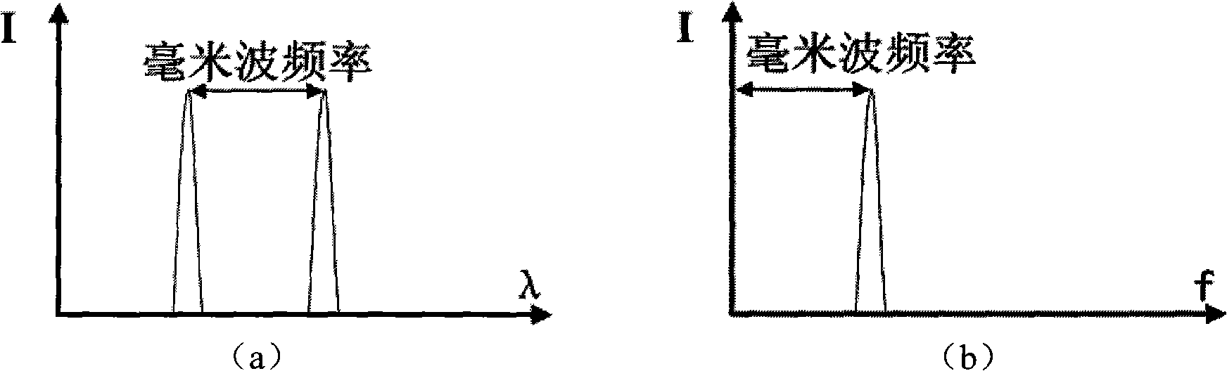
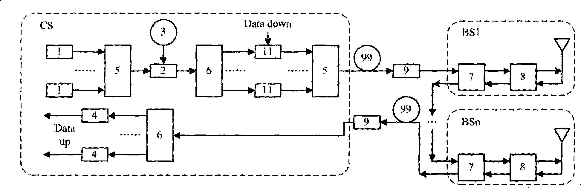
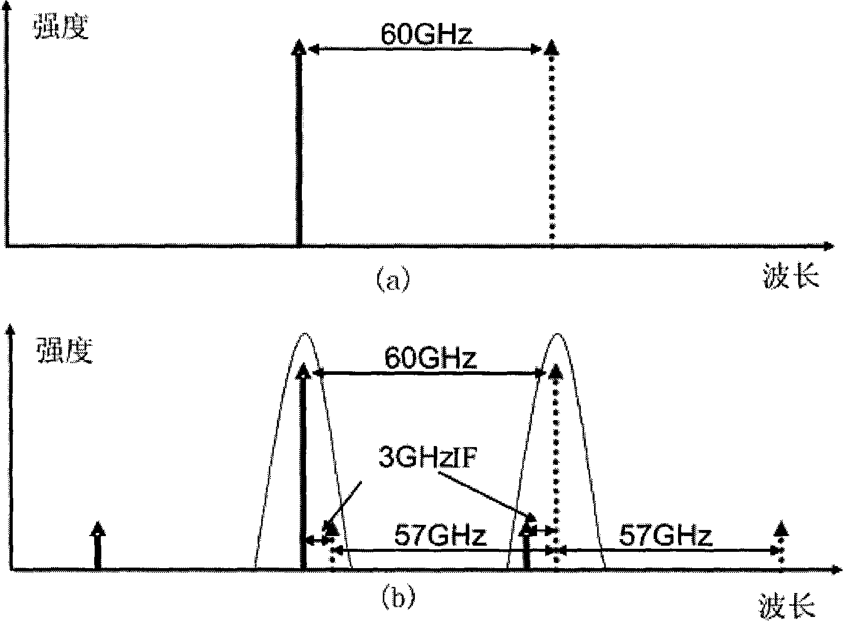
[0076] Such as Figure 5 As shown, the center wavelength of communication between a certain base station and the central station is the standard wavelength in the ITU-T standard channel. The wave frequency is 60GHz. The downlink of the system base station includes an optical differential multiplexer (OADM) and a high-speed photoelectric detector. The dual longitudinal mode optical signal of the downlink enters the corresponding base station from the ring optical fiber network through the optical differential multiplexer, and then obtains the millimeter-wave radio frequency (RF) signal by optical beat frequency on the high-speed photodetector, and passes through the high-frequency cable Connect the antenna to transmit. The system base station uplink includes an optical coupler, an optical circulator, an optical polarization controller, and a Fabry-Perot (FP) laser with a millimeter-wave RF direct current modulation interface, and its longitudinal mode spacing is 60 GHz . Se...

Embodiment 2

[0078] Such as Figure 6 As shown, the center wavelength of communication between a certain base station and the central station is the standard wavelength in the ITU-T standard channel. The wave frequency is 60GHz. The downlink of the system base station includes an optical differential multiplexer (OADM) and a high-speed photoelectric detector. The dual longitudinal mode optical signal of the downlink enters the corresponding base station from the ring optical fiber network through the optical differential multiplexer, and then obtains the millimeter-wave radio frequency (RF) signal by optical beat frequency on the high-speed photodetector, and passes through the high-frequency cable Connect the antenna to transmit. The system base station uplink includes an optical coupler, an optical polarization controller, and a traveling-wave Fabry-Perot (FP) laser with a millimeter-wave RF direct current modulation interface, and its longitudinal mode spacing is 60 GHz. Separate a s...


PUM


Abstract

The invention discloses a ROF base station uplink of a wavelength-multiplexing passive optical network and its system, belonging to the optical communication field. The uplink comprises an optical coupler for coupling a part of signals in the downlink to input into the multimode laser; a mode-locking multimode laser for generating double mode-locking mode optical signals with the mode distance of millimeter wave frequency. The uplink signals are directly loaded to the double mode-locking mode optical signals for transmission by modulating the multimode laser. The system comprises a central station and a plurality of base stations including the uplink chains. The invention reduces the wavelength occupancy rate, effect from the downlink to the uplink signals, improves the modulation bandwidth, and decreases the equipment costs, realizes the amplification of the downlink double mode carrier wave, filtering and increasing of the optical carrier signal to noise ratio.

Description

technical field [0001] The present invention relates to a radio-over-fiber wireless signal (Radio-over-Fiber, abbreviated as ROF) uplink and its communication system, in particular to a base station of a novel radio frequency signal optical fiber transmission system based on a wavelength division multiplexing passive optical network An uplink and a system thereof belong to the field of optical communication. Background technique [0002] In recent years, with the rapid development of wireless communication, the number of wireless users has increased year by year, the services have become more diversified, and the data services have risen sharply, making the demand for broadband wireless signals and carrier frequencies to be extended to high frequencies increasingly urgent. At present, various electronic devices are limited by electronic bottlenecks, which are far from meeting the growth of future demand. Radioover Fiber (RoF for short) combines the huge capacity of optical ...

Claims


Application Information

Patent Timeline
Patent Type & Authority Applications(China)
IPC IPC(8): H04B10/17H04B10/155H04J14/02H04B10/2575H04Q11/00
Inventor 张诚胡薇薇陈章渊
Owner PEKING UNIV
Why Eureka
Try Eureka