
Method and device for exchanging time deterministic data based on time pressure

A technology of time pressure and data exchange, applied in the field of data exchange, can solve problems such as delay, delay jitter characteristics, reduced information exchange stability, high complexity of scheduling algorithm, etc., to eliminate HOL congestion, avoid input competition and output Race Problems, Effects of Requirements to Reduce Time Complexity

Inactive Publication Date: 2008-09-03
NAT UNIV OF DEFENSE TECH
View PDF0 Cites 10 Cited by
  • Summary
  • Abstract
  • Description
  • Claims
  • Application Information

AI Technical Summary

Problems solved by technology

Although various switching structures have their own advantages, however, the output queuing switching structure has the problem of N times acceleration, and its application is limited in high-speed environments. Increasing the speed will greatly increase the cost, and the stability of information exchange will be reduced as the speed increases; Although the input queuing switching structure does not need to be accelerated, the scheduling algorithm of the input queuing switching structure can only achieve coarse-grained priority services, and its delay and delay jitter characteristics are not as good as the scheduling algorithm based on the output queuing switching structure; joint input and output queuing The switching structure is only in the theoretical research stage, and the complexity of its scheduling algorithm is too high, which is difficult to realize in engineering; A cache unit with a certain capacity enables each input port and output port of the switching unit to use internal connection bandwidth resources relatively independently, avoiding a centralized control mechanism, and providing a better basic platform for improving the overall performance of switching devices

Method used


Image

  • Method and device for exchanging time deterministic data based on time pressure
  • Method and device for exchanging time deterministic data based on time pressure
  • Method and device for exchanging time deterministic data based on time pressure

Examples


Embodiment Construction

[0044] The present invention will be described in further detail below in conjunction with the accompanying drawings and specific embodiments.

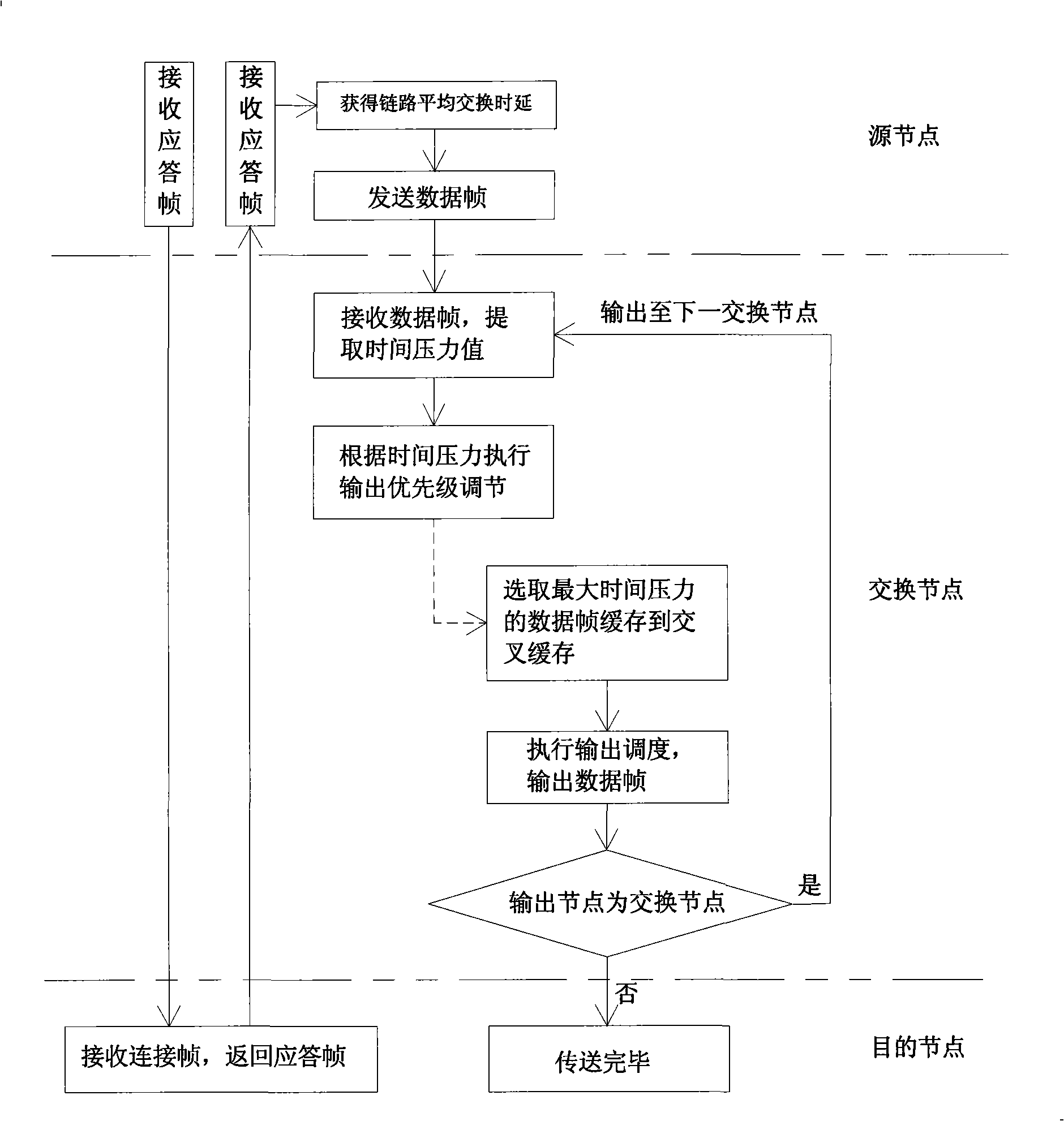
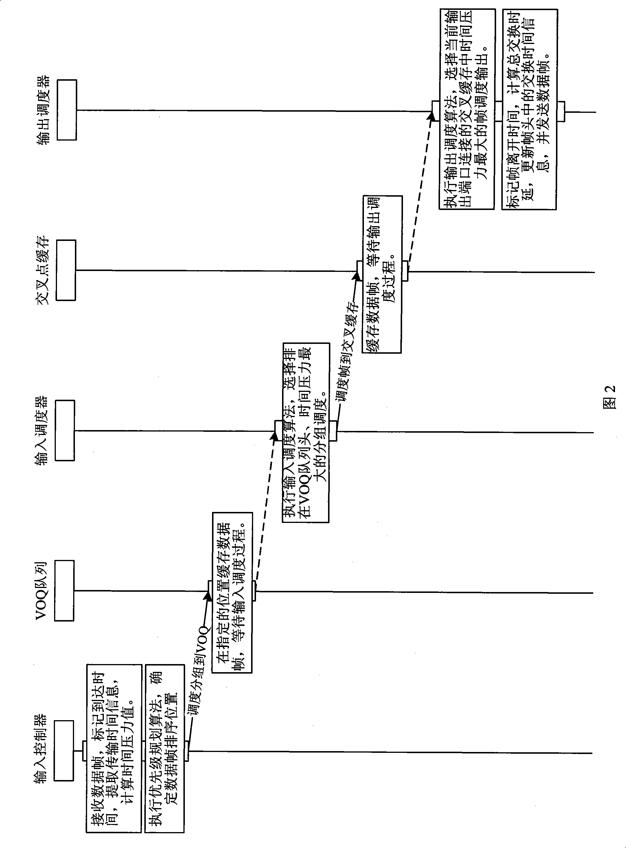
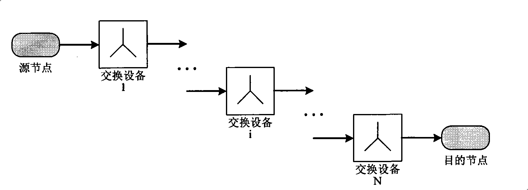
[0045] Such as figure 1 and image 3 As shown, a data transmission link used for data transmission in the network environment constructed by switching equipment is composed of one source node, one or more switching devices and one destination node. The method of time-deterministic data exchange is: in the network environment constructed by switching nodes, measure the total switching delay and the number of switching nodes passed by each data frame in real time, and record the data frames together. Each switching node calculates the switching time pressure of the data frame based on the actual transmission delay requirements of the data frame and the above-mentioned switching node number and total switching delay recorded in the data frame, and based on the time pressure The switching priority is adjusted and controlled to ensure th...


PUM


Abstract

Disclosed is a time deterministic data switching method and device based on time pressure. The method comprises: in the network environment constructed by switching nodes, real time measuring the total switching delay and the switching node number generated by transmitting each data frame through each switching node, recording the delay and the node number onto the data frame and transmitting the same; calculating the switching time pressure of the data frame by each switching node according to the actual transmission delay requirement, and the total switching delay and the switching node number recorded in the data frame; adjusting and controlling the switch priority based on the time pressure to satisfy the transmission delay requirement needed by the data frame. The switching device includes a switching module, a time module, a storage unit and a PHY module. The invention can achieve dynamic coordination of the switch delay among the multiple switching devices, ensure the determinacy and the consistency of data end-end transmission relay, and improve the transmission efficiency and stability.

Description

technical field [0001] The present invention mainly relates to the field of data exchange methods in a network environment constructed by exchange equipment, in particular to a time-deterministic data exchange method and exchange device based on time pressure, especially suitable for deterministic end-to-end data transmission delay Required network measurement and control systems, such as real-time measurement, network control, industrial automation, and field testing methods for time-deterministic data exchange. Background technique [0002] The store-and-forward mechanism, queue structure, and scheduling algorithm of existing switching devices lead to uncertainty in data exchange delay, and in a data transmission link formed by interconnecting multiple switching devices, since each switching device completes the In the scheduling process, there is no coordination of data transmission status among each other, resulting in greater uncertainty of end-to-end data transmission ...

Claims


Application Information

Patent Timeline
IPC IPC(8): H04L12/56H04L1/00H04L12/801
Inventor 黄飞乔纯捷钟小鹏王跃科明德祥杨俊陈建云杨建伟
Owner NAT UNIV OF DEFENSE TECH
Learn More