Manufacturing method for embedding heat radiating fin on printed circuit board

A technology of printed circuit boards and manufacturing methods, which is applied in the fields of printed circuit manufacturing, printed circuit, multilayer circuit manufacturing, etc., can solve problems such as difficult processing, metal offset, abnormal grinding board, etc., and solve the problems of circuit board surface Concave or protrude, reduce abnormal wear, good embedding effect

Inactive Publication Date: 2008-09-03
CHINA CIRCUIT TECH SHANTOU CORP
View PDF0 Cites 27 Cited by
  • Summary
  • Abstract
  • Description
  • Claims
  • Application Information

AI Technical Summary

Problems solved by technology

[0006] In the above process, since the multi-layer circuit board is pressed first, and then drilled on the laminated multi-layer circuit board, the processing is difficult; at the same time, due to the thermal curing of the liquid resin, it is easy to appear resin voids, metal Offset, and because the height of the heat sink is inconsistent with the thickness of the circuit board, when the heat sink is embedded in the circuit board, the surface of the circuit board is prone to depression or protrusion, so problems such as abnormal grinding of the board are prone to occur

Method used


Image

  • Manufacturing method for embedding heat radiating fin on printed circuit board
  • Manufacturing method for embedding heat radiating fin on printed circuit board
  • Manufacturing method for embedding heat radiating fin on printed circuit board

Examples


Embodiment 1

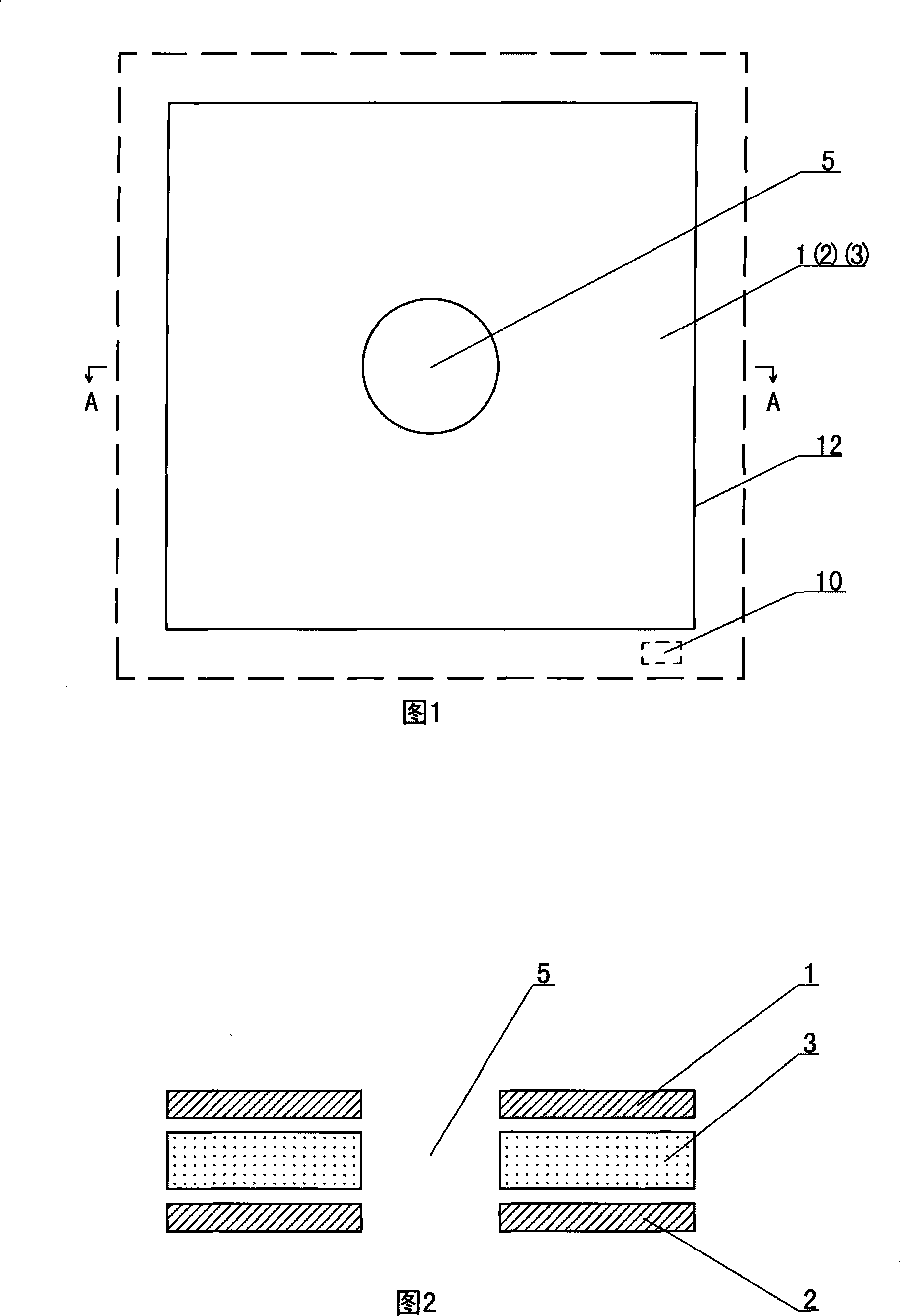
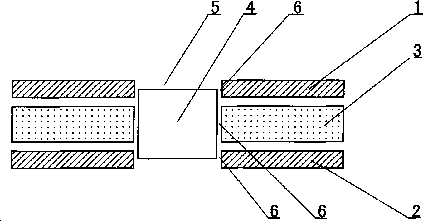
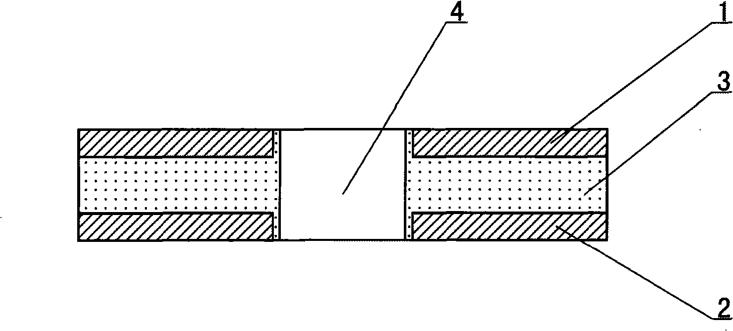
[0031] Figure 1 to Figure 4 As shown, a manufacturing method for embedding a heat sink on a printed circuit board includes the following steps:

[0032] 1) Open the tool hole 5 at the position of the pre-embedded heat sink 4 in the first circuit board 1, the prepreg 3 and the second circuit board 2 molding area 12 (the area in the solid line in Figure 1), and at the same time, in the first Drill a pre-alignment hole 10 outside the molding area 12 of the circuit board 1, the prepreg 3 and the second circuit board 2 (the area between the solid line and the dashed line in FIG. 1 );

[0033] The above-mentioned first circuit board 1 and second circuit board 2 are multilayer circuit boards, wherein there are at least two conductive layers and a conductive signal layer;

[0034] Above-mentioned tool hole 5 can adopt the mechanical processing of modes such as punching or drilling;

[0035] The above-mentioned prepreg 3 adopts a prepreg with a resin content of 63%;

[0036] Above-...

Embodiment 2

[0043] Such as Figure 5 to Figure 8 As shown, Embodiment 2 is a manufacturing method for embedding heat sinks on a printed circuit board with three circuit layers, comprising the following steps:

[0044] 1) Open the tool hole 5 at the position of the pre-embedded heat sink 4 in the molding area 12 of the first circuit board 1, the first prepreg 3, the second circuit board 2, the second prepreg 7 and the third circuit board 8, and at the same time, The first circuit board 1, the first prepreg 3, the second circuit board 2, the second prepreg 7 and the molding area 12 of the third circuit board 8 are drilled with pre-alignment holes 10;

[0045] The above-mentioned first circuit board 1, second circuit board 2 and third circuit board 8 are multilayer circuit boards, wherein there are at least two conductive layers and conductive signal layers;

[0046] Above-mentioned tool hole 5 can adopt the mechanical processing of modes such as punching or drilling;

[0047] Both the fir...


PUM


Abstract

A making method for embedding fins on a printed circuit board includes following steps: 1) opening a tool hole on the position to be embedded with fins in a circuit board and a prepreg forming region, and drilling a pre-positioning hole outside of the forming region; 2) arranging the prepreg between two adjacent circuit board, pre-positioning the circuit boards and the prepreg through the pre-positioning hole; 3) arranging fins in the tool hole in a stitching pre-lamination process; 4) stitching the circuit boards and the prepreg to fill the gap between the tool hole and fins by flowing latex, the prepreg cures automatically during stitching, combining the fins and the circuit boards; 5) mechanical brushing and grinding board elements, cleaning residual prepreg material on surfaces of circuit boards. The invention avoids the inanition phenomenon, solves depression or protrusion of circuit board surfaces, reduces abnormal wear of grinding brush wheels in following process, thereby the embedding effect of fins is good.

Description

technical field [0001] The invention relates to a method for manufacturing a printed circuit board, more specifically, to a method for manufacturing a heat sink embedded on a printed circuit board. Background technique [0002] The heat dissipation method of the traditional circuit board is to provide a heat sink (usually a metal sheet) on the back of the circuit board, and the heat emitted by the circuit board is dissipated through the heat sink, thereby achieving the purpose of cooling the circuit board. [0003] With the increasing complexity of circuit boards, the heat dissipation methods of traditional circuit boards can no longer meet the design requirements of circuit boards. [0004] Later, people directly embedded the heat sink into the circuit board to effectively realize local heat dissipation of the circuit board and reduce electromagnetic radiation interference. [0005] At present, the manufacturing method of embedding heat sinks in printed circuit boards gene...

Claims


Application Information

Patent Timeline
Patent Type & Authority Applications(China)
IPC IPC(8): H05K3/00H05K3/46H05K7/20
Inventor 何润宏邱彦佳
Owner CHINA CIRCUIT TECH SHANTOU CORP
Why Eureka
Try Eureka