
Safety guarding information system for airport aviation area

An information system and flight zone technology, applied in CCTV systems, telephone communications, instruments, etc., can solve the problems of inability to quickly and accurately lock the target, prone to false positives and false negatives, slow rotation of the gimbal, etc., to achieve coordination The effect of improving sexual and police response ability, good effect and high sensitivity

Inactive Publication Date: 2008-09-10
SHENYANG HUITONG ZHILIAN ELECTRONICS ENG DESIGN & INSTALLATION
View PDF0 Cites 21 Cited by
  • Summary
  • Abstract
  • Description
  • Claims
  • Application Information

AI Technical Summary

Problems solved by technology

This preventive measure, first, electromagnetic interference (EMI) and radio frequency interference (RFI) have a great influence on the sensitivity of the vibrating cable, which is prone to false alarms and false alarms, and consumes a lot of power; second, infrared radiation Although the special material shell of the detector can filter out the interference of white light, it can’t do anything about the infrared part of the light interference source, especially when using ordinary transmissive or reflective lenses for focusing infrared light, when focusing infrared rays of a specific wavelength, At the same time, the light of all the characters is also focused, so it is still easy to cause false alarms; thirdly, in terms of auxiliary video surveillance system, the traditional bullet camera is large in size, the pan / tilt rotates slowly and has dead angles, so it cannot be locked quickly and accurately The target cannot achieve the effect of dynamic monitoring of the flight area without blind spots

Method used


Image

  • Safety guarding information system for airport aviation area
  • Safety guarding information system for airport aviation area
  • Safety guarding information system for airport aviation area

Examples


Embodiment Construction

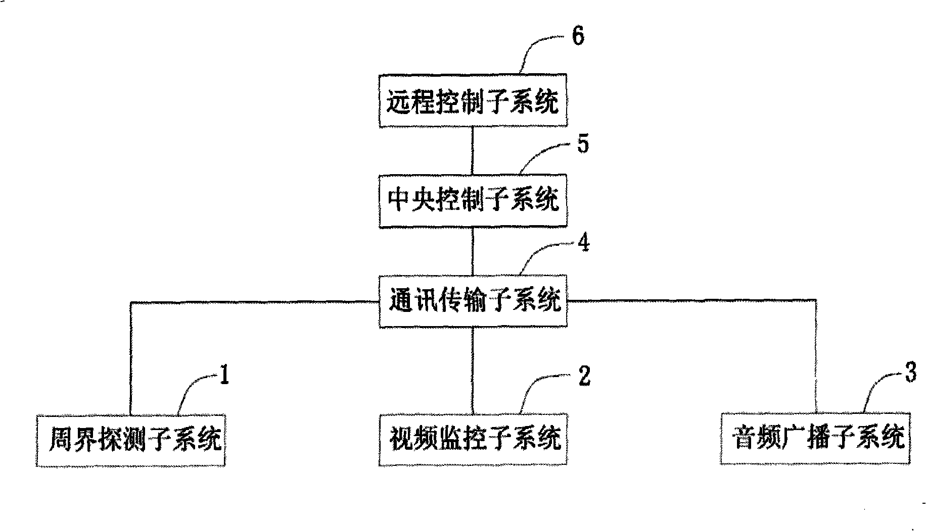
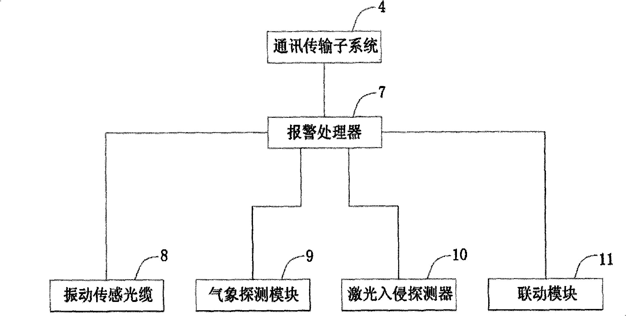
[0019]The flight area of ​​the airport is surrounded by steel guardrails with a height of about 2.5 meters. There is one defense area every 150 meters to 200 meters. Vibration sensing cables are installed at a height of about 1.5 meters on the fence, and two adjacent defense areas are configured. 1 dual-channel alarm analysis controller, its alarm output is connected to the on-site alarm controller, the on-site alarm controller has a built-in voice module, and its output controls the power amplifier module and the broadcast speaker; the on-site alarm controller also has node output to the broadcast speaker Driver module and lighting driver module. There is a movable door in the enclosure, and a laser intrusion detector is used for protection, and the alarm signal is connected to the corresponding alarm processor on site.

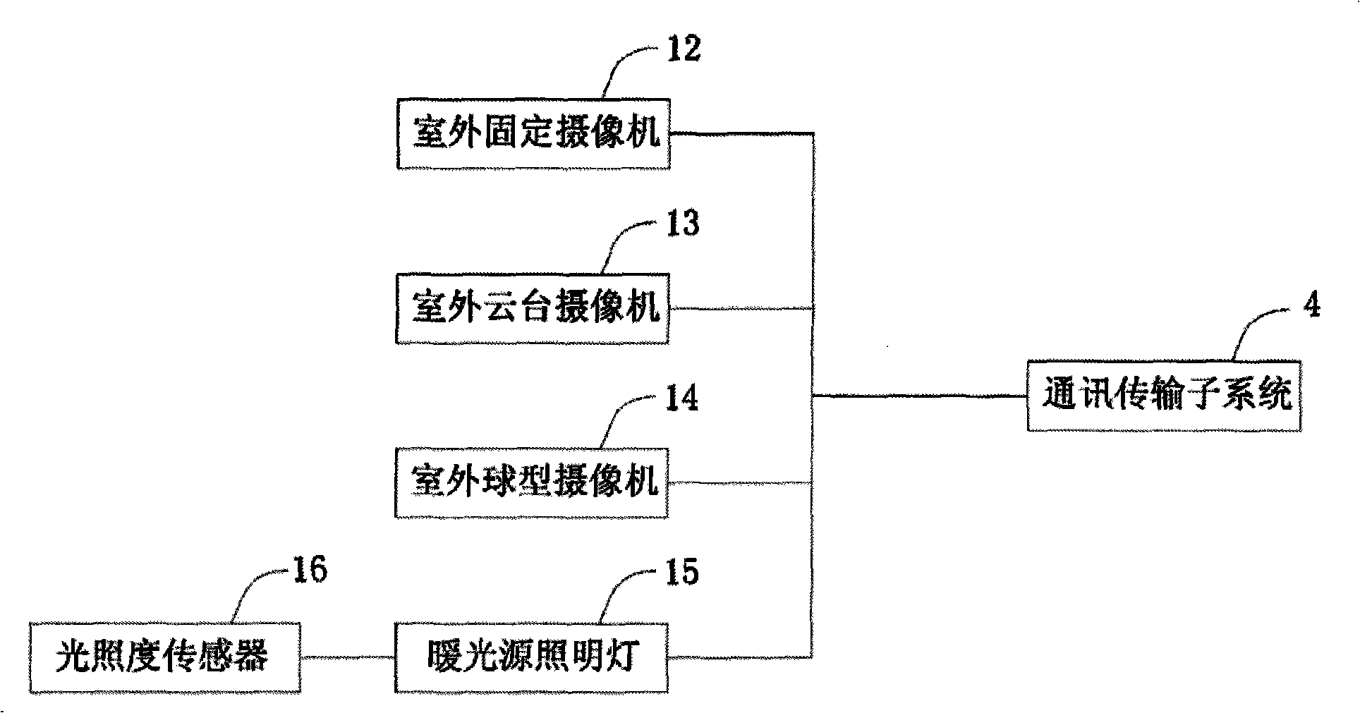
[0020] This system adopts outdoor high-speed intelligent dome cameras in the camera subsystem of the enclosure, and can set the capture point preset positio...


PUM


Abstract

A security information system of a flight area of an airport comprises a perimeter detection subsystem, a video monitor subsystem, an audio broadcasting subsystem, a communication transmission subsystem, a central control subsystem and a remote control subsystem. The system resolves the problem of 'isolate island' phenomenon among subsystems in a former system and improves the cooperativeness and the response capability of police service of the whole system. The system organically combines all components through the communication transmission subsystem to realize coordination working of all the subsystems immediately when an alarm occurs, thereby forming a close, complete and perfect security information system. By adopting the double loop bus technology and the optical fiber as information transmission carrier and applying processing of computer digital signals, video imaging and audio signals, the system realizes a field integrated information system with a unification of three nets. The system has the advantages of strong stability, high sensitivity, high intelligence and convenient operation and maintenance, etc.

Description

Technical field [0001] The invention relates to a security protection system for airports, in particular to a network information system which can be used for security protection in the flight area of ​​airports. Background technique [0002] In the security system of the prior art, each branch part presents an "island" phenomenon, and each part generally exists only to realize a specific function, and cannot be compatible and integrated with each other. This independent state affects the overall coordination of the system and the response time of the police. When dealing with alarm problems, it is impossible to achieve the linkage effect of "pulling one hair and moving the whole body". In the perimeter defense of the flight area, the original method mostly used vibrating cables and infrared beam detectors for defense, and traditional bullet cameras were used for auxiliary video monitoring. This precautionary measure, first, electromagnetic interference (EMI) and radio fre...

Claims


Application Information

Patent Timeline
IPC IPC(8): G08B19/00G08B25/00H04N7/18H04M11/00
Inventor 汤祖福李欣然项正辉曹喜国
Owner SHENYANG HUITONG ZHILIAN ELECTRONICS ENG DESIGN & INSTALLATION
Learn More