Adjustable laser coaxial powder feeding nozzle

A coaxial powder feeding and adjustable technology, applied in the field of laser coaxial powder feeding nozzles and laser metal direct manufacturing nozzles, can solve the problems of low powder utilization rate and poor powder convergence effect, so as to improve the cooling effect and promote The effect of powder gathering and avoiding short circuit

Inactive Publication Date: 2008-09-17
XI AN JIAOTONG UNIV
2 Cites 55 Cited by

AI-Extracted Technical Summary

Problems solved by technology

[0005] In view of the fact that the laser metal direct manufacturing puts forward higher requirements for the coaxial powder feeding nozzle, the powder sent by the coaxial powder feeding nozzle is required to be more evenly distributed in the circumferential direction and has good convergence: in order to prolong the service life of the nozzle, it is required to The axial powder feeding nozzle has a good cooling effect; therefore, the purpose of the present inventi...

Method used

[0026] The inner side of the end of the laser sleeve 8 adopts a stepped structure to form a laser channel, which reduces the difficulty of manufacturing from the production process. The upper part of the laser sleeve 8 adopts a flange structure. The flange plate and the adjustment base 11 constitute the main body of the centering adjustment mechanism. There are four adjustment screws 10 on the adjustment base 11 corresponding to the height of the flange. Using the adjustment screws 10, the laser beam Adjust the centering of the nozzle laser sleeve as the center, and lock it with the lock nut 9. This adjustment mechanism ensures the alignment between the laser focus and the powder focus. The adjustment base 11 is connected with the lifting inner sleeve 12 through threaded connection, and a deformed screw nut mechanism is formed between the lifting inner...

Abstract

The invention discloses an adjustable coaxial laser nozzle for sending powder, comprising a laser head, a protection lens, a water-cooling sleeve for the protection lens and a column laser cavity arranged on the upper part, a coaxial conical laser cavity which is formed by the inner layer of a laser sleeve and arranged in the middle part, wherein a powder cavity, a secondary external protective cavity and an external water-cooling cavity are arranged on the lower part of the external part of the laser sleeve; the powder cavity is formed between the laser sleeve and a power cavity sleeve screwed together; the secondary external protective cavity is formed between the powder cavity and a protective air casing screwed together; the powder cavity and the protective sir casing are screwed together and adjustable between 1mm to 3mm; 4 to 6 power transmitting pipes and 4 to 6 air tubes are respectively positioned around the top parts of the cones of the powder cavity and the protective air cavity. The adjustable coaxial laser nozzle for sending powder has the advantages that the focus length of the focus lamp fit for the coaxial powder-sending nozzle is between 100mm to 300mm, which ensures convenient assembly and disassembly, even velocity, flexible adjustment of the powder converge diameter, convenient changeable lower coaxial conical parts (the powder cavity, the air casing and the water cavity).

Technology Topic

Laser NozzleOptoelectronics +5

Image

  • Adjustable laser coaxial powder feeding nozzle
  • Adjustable laser coaxial powder feeding nozzle
  • Adjustable laser coaxial powder feeding nozzle

Examples

  • Experimental program(1)

Example Embodiment

[0023] The present invention will be further described in detail below in conjunction with the accompanying drawings and embodiments.
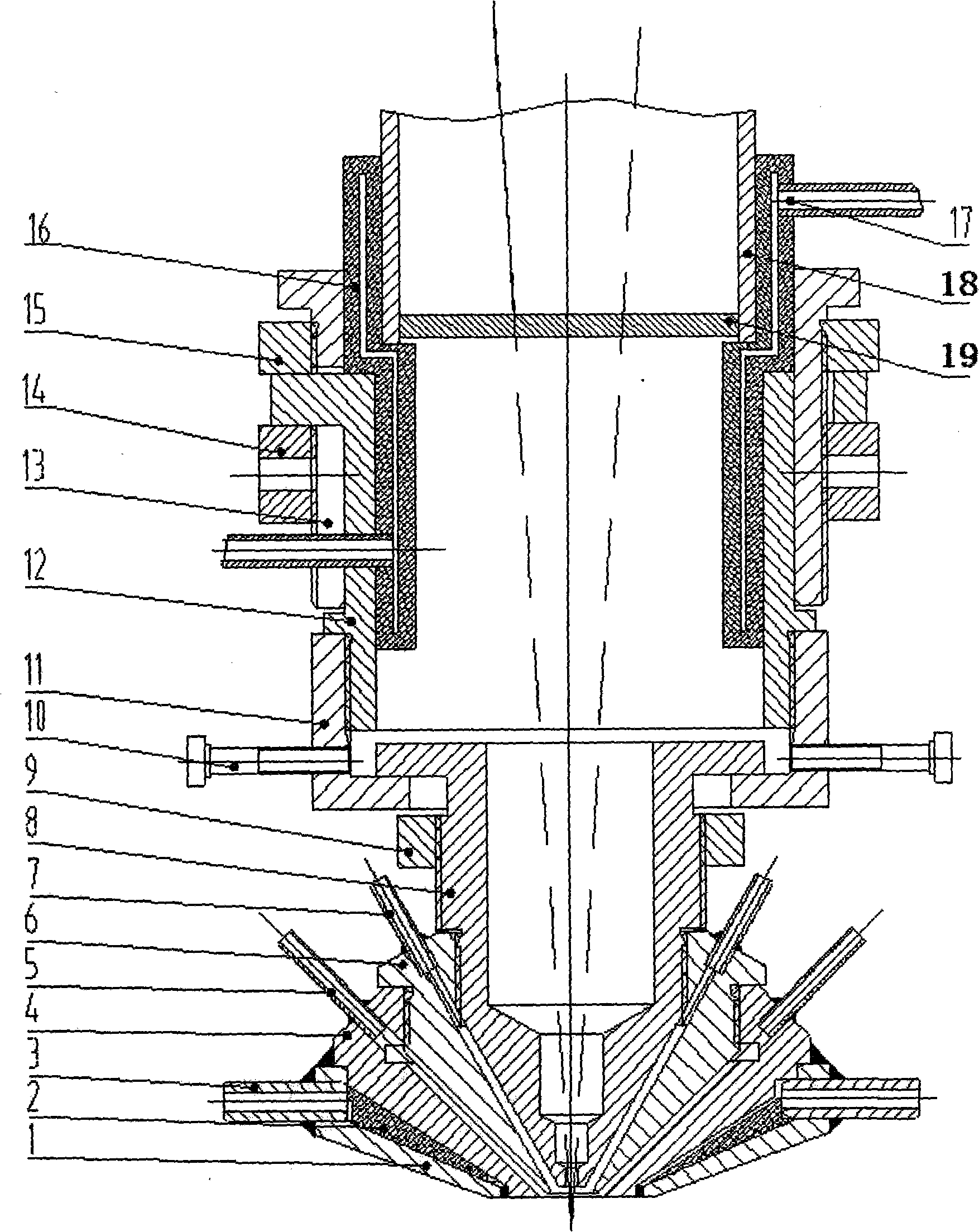
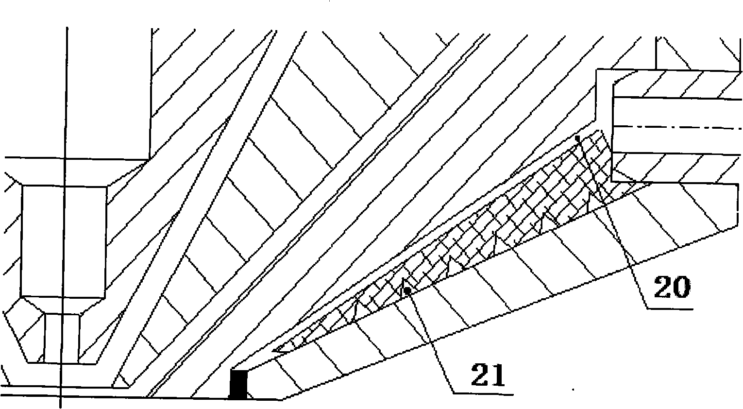
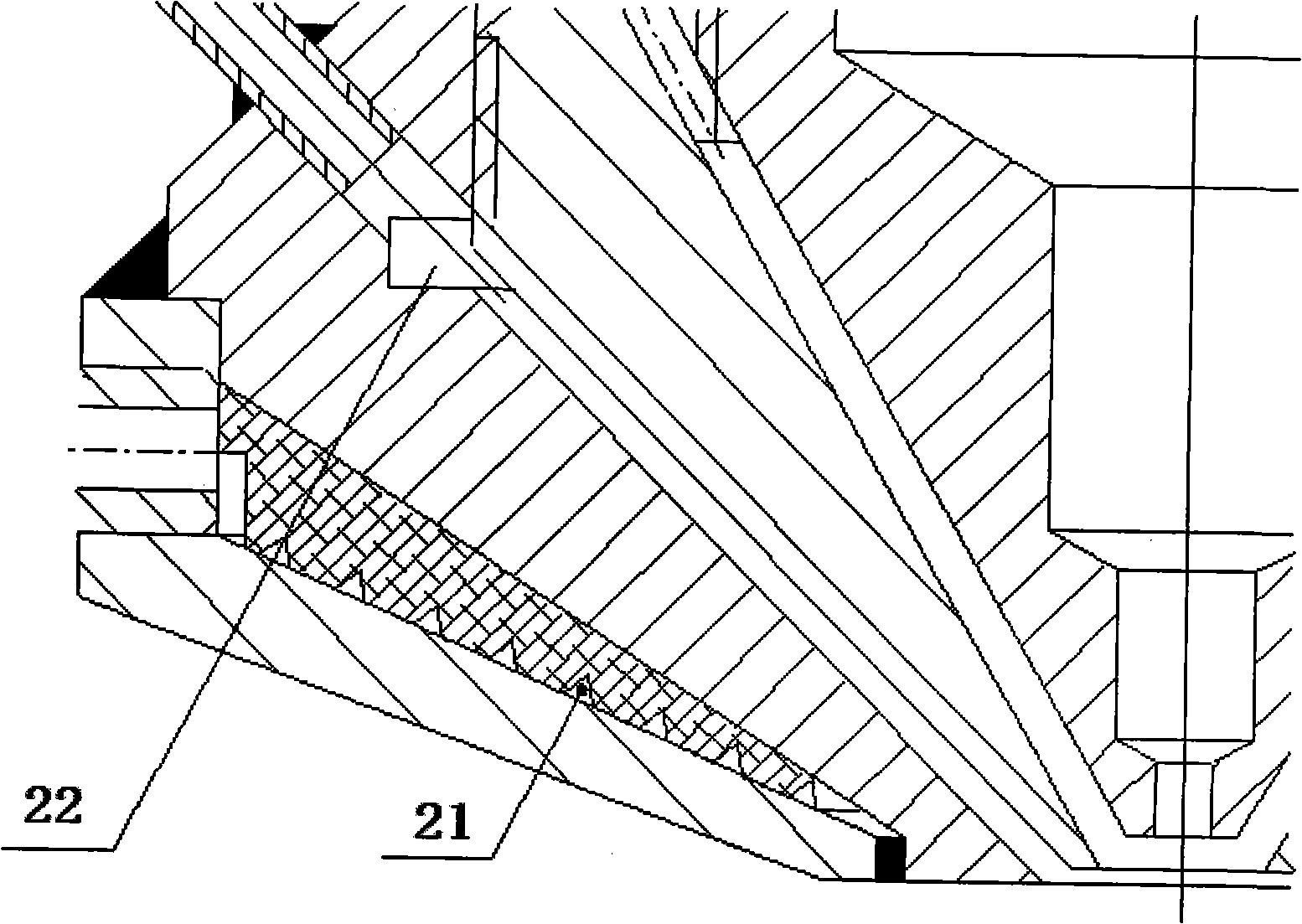
[0024] as attached figure 1 , figure 2 and image 3 As shown in the figure, the present invention is characterized in that the lower part of the coaxial powder feeding nozzle is composed of a nozzle water cooling jacket 1, a protective gas jacket 4, a powder cavity jacket 6 and a laser jacket 8, and the upper part of the coaxial powder feeding nozzle is composed of a centering adjustment base 11. It is composed of lifting inner and outer sleeves 12, 13, a water cooling jacket 16 of the protective mirror and two threaded clamps. The nozzle water cooling jacket 1 is welded with cooling water inlet and outlet pipes 3 on its cylindrical part. The nozzle water cooling jacket 1 and the protective gas jacket 4 form a water cooling chamber. In order to prevent the phenomenon of "short-circuit circulation" of cooling water in the water-cooling cavity, a water-dividing screw block 2 is arranged in the water-cooling cavity. The cooling water conducts convective heat exchange. The cooling water pipes 3 (inlet and outlet pipes) differ by 180°. The inlet of the water inlet channel and the outlet of the spiral outlet channel on the water dividing screw block 2 correspond to the water inlet pipe and the water outlet pipe respectively.
[0025] The protective air sleeve 4 and the powder chamber body sleeve 6 are connected by thread to form a protective air chamber, the thickness of the protective air chamber can be adjusted between 1 and 3 mm, and 4 to 6 air supply pipes 5 are evenly distributed on the protective air chamber. An annular groove 22 is formed on the conical surface of the protective gas jacket 4 at the outlet, and the annular groove 22 can promote the uniform distribution of the protective gas in the air cavity. The included angle between the protective gas cavity and the axis of the laser cavity is 20-45°. The powder cavity sleeve 6 and the laser sleeve 8 are connected by threads to form a powder cavity. The thickness of the powder cavity can be adjusted between 1 and 3 mm. It can be adjusted steplessly during adjustment, and can also be adjusted through a standard washer. There are 4 to 6 powder feeding pipes 7 evenly distributed on the powder cavity. The included angle between the powder cavity and the axis of the laser cavity is 15-30°. The axes of the powder feeding pipe 7 and the gas feeding pipe 5 are tangent to the powder cavity and the protective gas cavity respectively, which is conducive to the spraying of powder and protective gas from the nozzle. Uniform extraction of nozzles provides assurance.
[0026]The inner side of the end of the laser sleeve 8 adopts a stepped structure to form a laser channel, which reduces the difficulty of production and manufacturing from the production process. The upper part of the laser sleeve 8 adopts a flange structure. The flange plate and the adjustment base 11 constitute the main body of the centering adjustment mechanism. There are four adjustment screws 10 on the adjustment base 11 corresponding to the height of the flange. Adjust the center of the nozzle laser sleeve as the center, and lock it with the lock nut 9. This adjustment mechanism guarantees centering between the laser focus and the powder focus. The adjusting base 11 is connected to the inner lifting sleeve 12 through a threaded connection, and a deformed lead screw nut mechanism is formed between the lifting inner sleeve 12 , the lifting outer sleeve 13 , the lifting nut 14 and the pressing nut 15 . The lifting mechanism in the nozzle ensures the coincidence of the laser focus and the powder convergence point and the adjustment of the defocus amount. The specific structure is: open four evenly distributed grooves on the lifting outer sleeve 13, and correspondingly extend four short claws on the outer circumference of the top of the lifting inner sleeve 12, and the four short claws are in the four Movement in the groove, the outer diameter of the lift inner sleeve 12 and the inner diameter of the lift outer sleeve 12 are clearance fit, the outside of the lift outer sleeve 13 is threaded, the lift nut 14 and the compression nut 15 are screwed on the lift outer sleeve 13, the four short claws of the lifting inner sleeve 12 are located between the lifting nut 14 and the pressing nut 15.
[0027] Considering the absorption, processability, weldability and thermal conductivity of the material to the laser, the manufacturing material of the powder feeding nozzle of the present invention mainly uses red copper or brass (copper has a very high reflectivity to the laser, excellent thermal conductivity, and is easy to process and welding).

PUM

PropertyMeasurementUnit
Angle15.0 ~ 30.0deg
tensileMPa
Particle sizePa
strength10

Description & Claims & Application Information

We can also present the details of the Description, Claims and Application information to help users get a comprehensive understanding of the technical details of the patent, such as background art, summary of invention, brief description of drawings, description of embodiments, and other original content. On the other hand, users can also determine the specific scope of protection of the technology through the list of claims; as well as understand the changes in the life cycle of the technology with the presentation of the patent timeline. Login to view more.

Similar technology patents

Classification and recommendation of technical efficacy words

  • Improve uniformity
  • Avoid short circuit
Why Eureka
Try Eureka