Voltage increase high-frequency link reverser
What is Al technical title?
Al technical title is built by PatSnap Al team. It summarizes the technical point description of the patent document.
A high-frequency inverter and high-frequency chain technology, applied in the field of boosted high-frequency chain inverter and power electronic conversion, can solve the problems that have not yet been seen, and achieve the effects of light weight, two-way power flow, and strong load adaptability.
Inactive Publication Date: 2010-07-21
FUZHOU UNIV
View PDF3 Cites 5 Cited by
Summary
Abstract
Description
Claims
Application Information
AI Technical Summary
This helps you quickly interpret patents by identifying the three key elements:
Problems solved by technology
Method used
Benefits of technology
Problems solved by technology
However, people's research on Boost converters is mainly limited to DC-DC conversion (such as "A soft-switching active-clamp scheme for isolated full-bridge boost converter" proposed by En-Sung Park et al., IEEE APEC, 2004, pp.1067~1070.) and AC-DC conversion (such as "Novel current-loop feed-forward compensation for boostPFC converter" proposed by Manjing Xie et al., IEEE APEC, 2004, pp.750~755.), for Boost type The research on high-frequency chain DC-AC conversion technology has not yet been seen
Method used
Image
Click on the blue label to locate the original text in one second.
Reading with bidirectional positioning of images and text.
Examples
Embodiment Construction
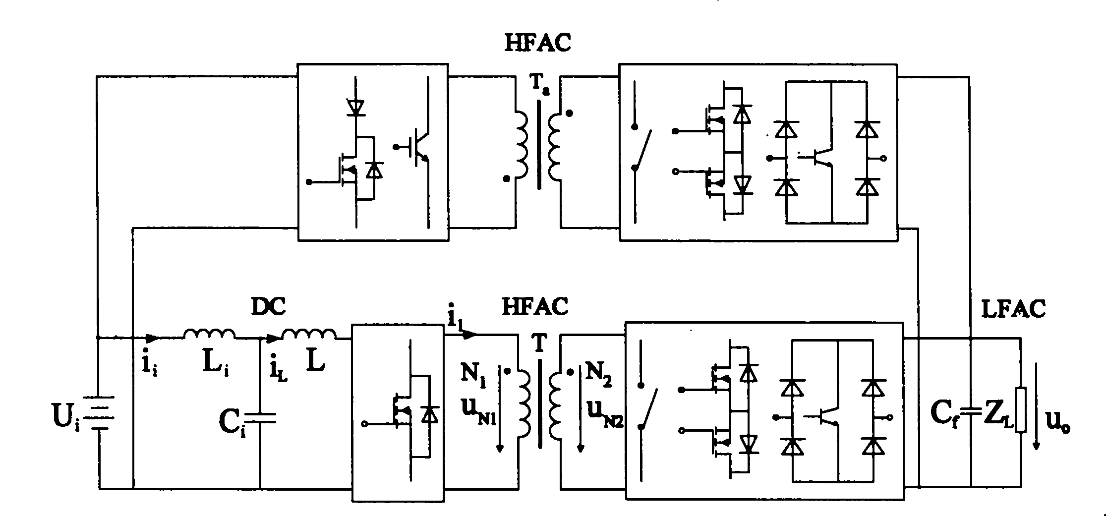
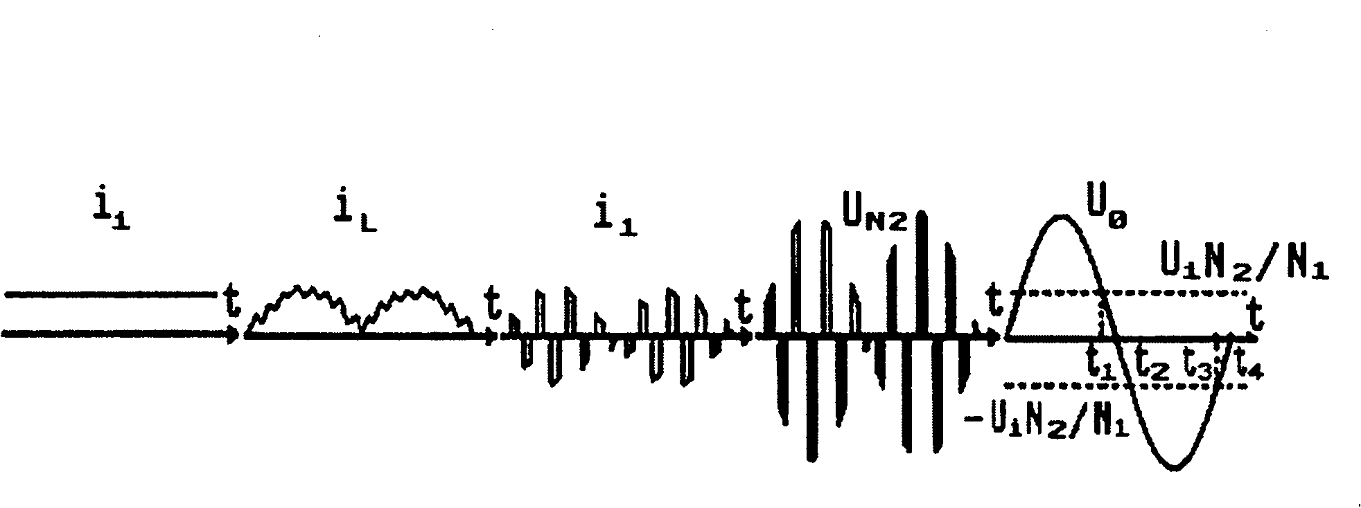
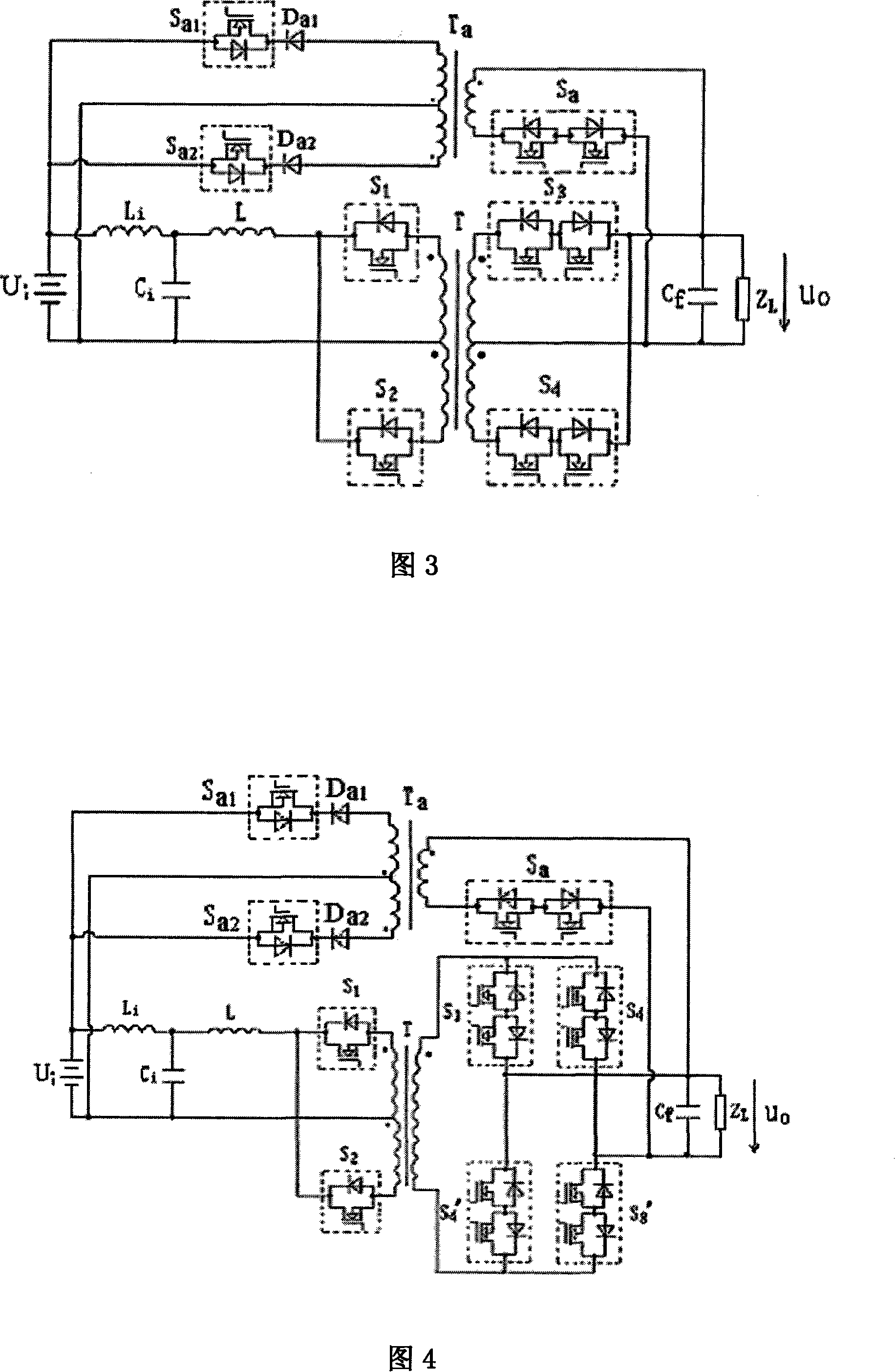
[0022] The boost (Boost) type high-frequency chain inverter circuit structure of the present invention is composed of an input filter circuit, an energy storage inductor, a high-frequency inverter, a high-frequency transformer, a cycloconverter, and an output filter circuit connected in sequence, and A high-frequency electrical isolation flyback converter energy feedback circuit is connected between the output load and the input DC power supply, and the high-frequency electrical isolation flyback converter energy feedback circuit consists of a cycloconverter and a high-frequency energy storage transformer 1. The rectifiers are cascaded in sequence, the input end of the cycloconverter is connected to the output load, and the output end of the rectifier is connected to the input DC power supply. The circuit topology of the high-frequency link inverter is push-pull full-wave, push-pull bridge, half-bridge full-wave, half-bridge, full-bridge full-wave or full-bridge circuit.
[00...
PUM
Abstract
The present invention provides a step-up high-frequency link inverter, the circuit structure is composed of an input filter circuit, a dumping inductor, a high-frequency inverter, a high frequency transformer, a frequency current converter, an output filter circuit cascaded in orders, a high frequency electrical isolation fly-back converter energy feedback circuit composed of the frequency current converter, the high frequency energy storage transformer, the rectifier cascaded in orders is connected between the output load and the input DC power, capable of transforming the unstable DC voltage to the needed stable sinusoidal voltage having high grade, the inverter has advantages of high frequency electrical isolation, high output and input voltage matching ability, double-directional power flow, high transforming efficiency, small volume, light weight, small input current ripple, high load adaptability, lower audio noise, high credibility when the load is shortened, lower cost, large output capacity, wide application, establishing a critical technique for the new type inverter and static inverter having large capacity.
Description
technical field [0001] The boost type high-frequency chain inverter involved in the present invention belongs to the power electronic conversion technology. Background technique [0002] Buck (Forward), Boost (single-ended Boost) and Buck-Boost (Flyback) are the three most basic and commonly used converter types, and their performance is shown in Table 1. Table 1 fully shows that although the Buck (Forward) converter has a large output capacity, it has defects such as large input current ripple and low reliability of the converter when the load is short-circuited; although the Buck-Boost (Flyback) converter has The converter has high reliability, but has defects such as large input current ripple and small output capacity; Boost (single-ended Boost) converter has the advantages of small input current ripple, high reliability when the load is short-circuited, and large output capacity. Buck (Forward) and Buck-Boost (Flyback) converters have large input current fluctuations, ...
Claims
Application Information
Patent Timeline
Application Date:The date an application was filed.
Publication Date:The date a patent or application was officially published.
First Publication Date:The earliest publication date of a patent with the same application number.
Issue Date:Publication date of the patent grant document.
PCT Entry Date:The Entry date of PCT National Phase.
Estimated Expiry Date:The statutory expiry date of a patent right according to the Patent Law, and it is the longest term of protection that the patent right can achieve without the termination of the patent right due to other reasons(Term extension factor has been taken into account ).
Invalid Date:Actual expiry date is based on effective date or publication date of legal transaction data of invalid patent.