Method, wireless sensor network system and synchronization device for realizing synchronization collection
A wireless sensor and synchronization device technology, which is applied to synchronization devices, transmission systems, digital transmission systems, etc., can solve the problems of inability to ensure that wireless sensor network nodes can collect data synchronously, time inconsistency, and inability to collect data.
- Summary
- Abstract
- Description
- Claims
- Application Information
AI Technical Summary
Problems solved by technology
Method used
Image
Examples
no. 1 example
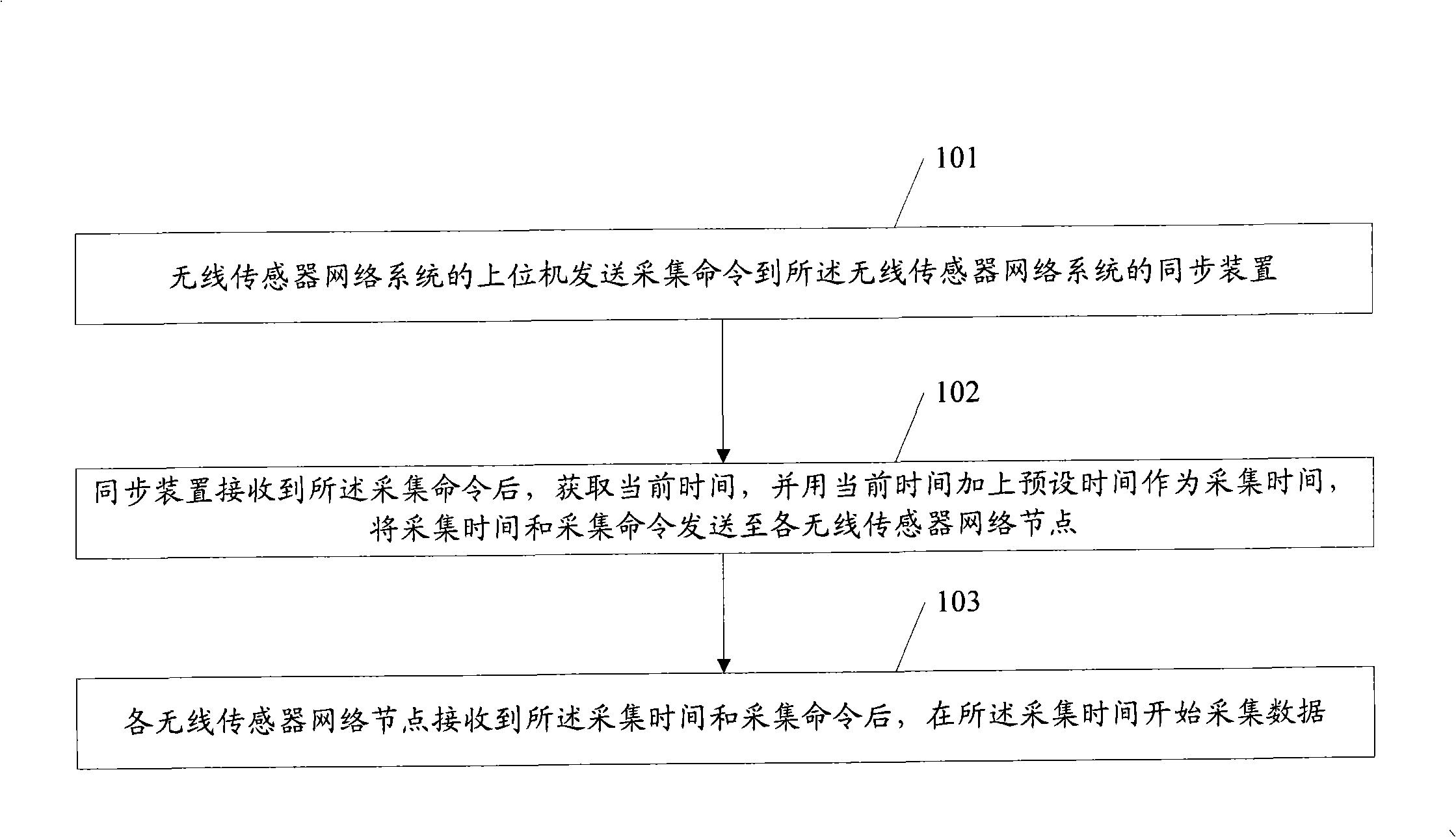
[0027] figure 1 The flow chart of the method for realizing synchronous acquisition provided by the embodiment of the present invention, such as figure 1 Shown:
[0028] Step 101: The upper computer of the wireless sensor network system sends a collection command to the synchronization device of the wireless sensor network system.
[0029] Step 102: After receiving the collection command, the synchronization device obtains the current time, uses the current time plus the preset time as the collection time, and sends the collection time and the collection command to each wireless sensor network node.
[0030] In this step, the synchronization device can obtain the current time in one of the following ways:
[0031] Way 1: The synchronization device obtains the current satellite time through GPS, and uses the current satellite time as the current time.
[0032] Mode 2: The synchronization device obtains the current reference time through a time reference circuit built with a c...
no. 2 example
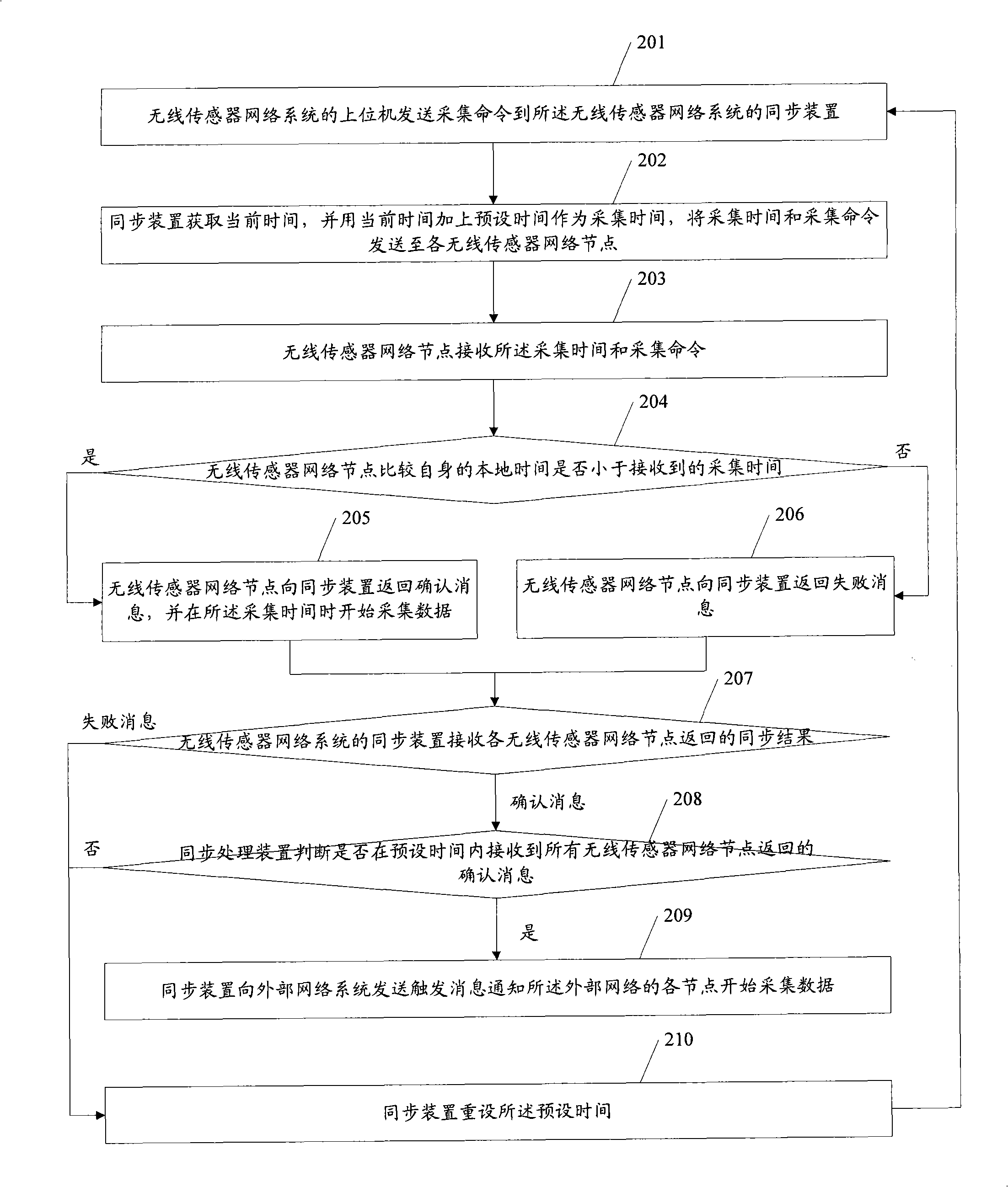
[0045] figure 2 The flow chart of the method for realizing synchronous acquisition provided by the embodiment of the present invention, such as figure 2 Shown:
[0046] Step 201: The upper computer of the wireless sensor network system sends a collection command to the synchronization device of the wireless sensor network system;
[0047] Step 202: After receiving the collection command, the synchronization device acquires the current time, uses the current time plus a preset time as the collection time, and sends the collection time and the collection command to each wireless sensor network node.
[0048] In this step, any one of the following methods can be used to realize the step of obtaining the current time by the synchronization device described above:
[0049] Way 1: The synchronization device obtains the current satellite time through GPS, and uses the current satellite time as the current time.
[0050] Mode 2: The synchronization device obtains the current refe...
no. 3 example
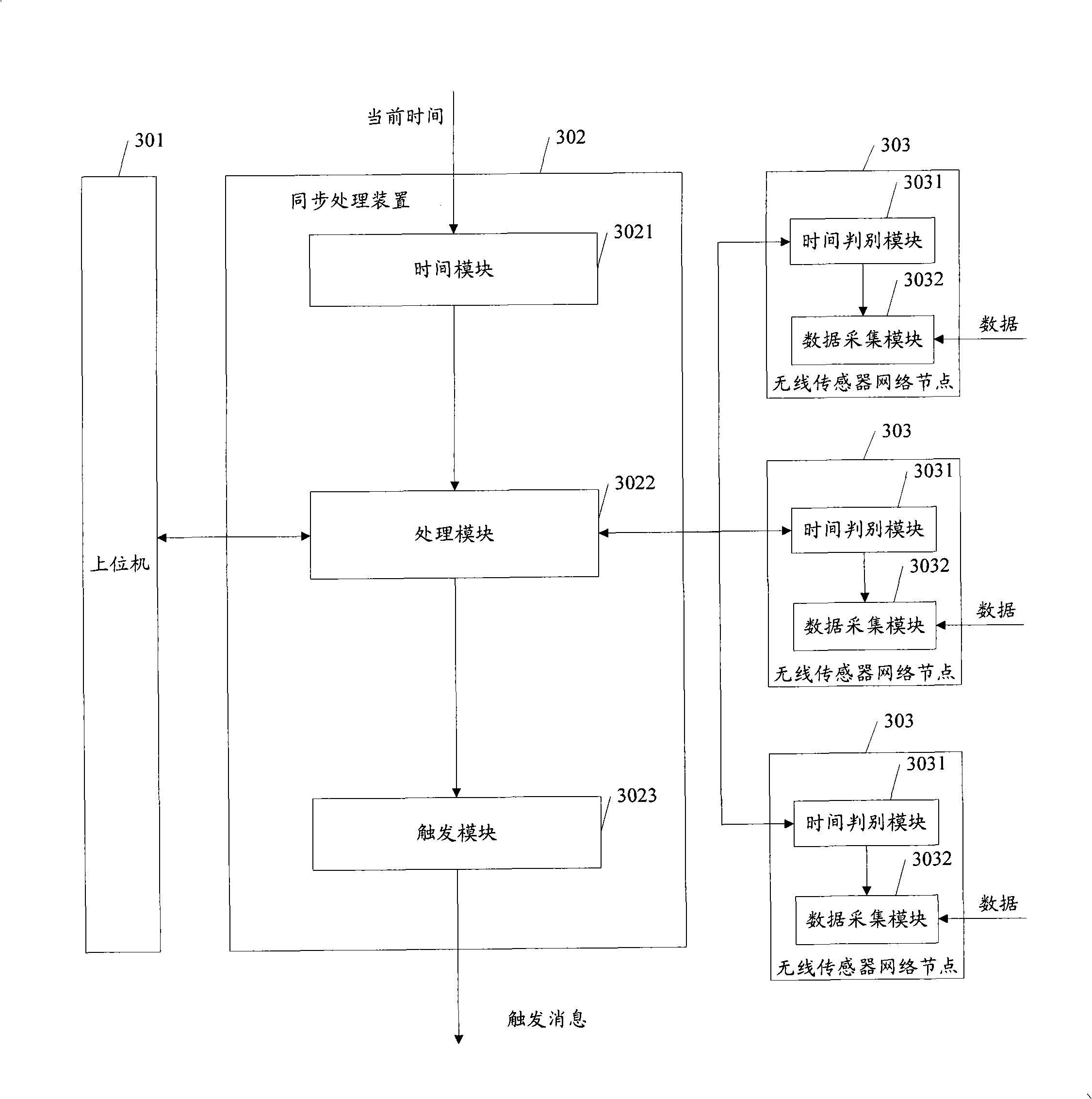
[0068] image 3 A structural diagram of a wireless sensor network system for realizing synchronous acquisition provided by an embodiment of the present invention. Such as image 3 Shown:
[0069] The wireless sensor network system for realizing synchronous acquisition provided by the embodiment of the present invention includes: a host computer 301 , a synchronization device 302 and a wireless sensor network node 303 .
[0070] The host computer 301 is used to send acquisition commands to the synchronization device 302 of the wireless sensor network system.
[0071] The synchronization device 302 is used to receive the collection command from the upper computer 301, after receiving the collection command, obtain the current time, and use the current time plus the preset time as the collection time, and send the collection time and the collection command to each wireless sensor network Node 303.
[0072] The wireless sensor network node 303 is configured to receive the coll...
PUM
 Abstract
Description
Claims
Application Information
 - R&D
- Intellectual Property
- Life Sciences
- Materials
- Tech Scout
- Unparalleled Data Quality
- Higher Quality Content
- 60% Fewer Hallucinations
Browse by: Latest US Patents, China's latest patents, Technical Efficacy Thesaurus, Application Domain, Technology Topic, Popular Technical Reports.
© 2025 PatSnap. All rights reserved.Legal|Privacy policy|Modern Slavery Act Transparency Statement|Sitemap|About US| Contact US: help@patsnap.com


