Cone beam type of X-ray CT system for three-dimensional reconstruction

a ct system and x-ray technology, applied in tomography, instruments, nuclear engineering, etc., can solve the problems of deteriorating temporal resolution, artifacts on images, and problems of ct scanners, and achieve the effect of improving temporal resolution

Inactive Publication Date: 2005-06-14
KK TOSHIBA
View PDF11 Cites 47 Cited by
  • Summary
  • Abstract
  • Description
  • Claims
  • Application Information

AI Technical Summary

Benefits of technology

[0009]An object of the present invention is to provide, with due consideration to the drawbacks of the above conventional configurations, an X-ray system and a three-dimensional reconstruction method for cone-beam CT, which are capable of reducing artifacts resulting from movements of an object when a three-dimensional reconstruction algorithm for cone-beam CT is applied to medical CT and improving temporal resolution.
[0018]Accordingly, for applying the cone-beam-CT three-dimensional reconstruction algorithm to medical CT imaging, even when an object to be imaged moves during a scan, artifacts due to object's motion can be reduced without failure, while still improving temporal resolution.

Problems solved by technology

However, if the above-listed conventional cone-beam CT scanners are desired to be used as an actual CT scanner, such CT scanners will encounter problems resulted from the fact that an object, that is, a patient may move during a scan.
That is, when a universal three-dimensional reconstruction algorithm is applied to projection data to obtain images, without taking the object motion into consideration, artifacts arise on the images and temporal resolution deteriorates.

Method used


Image

  • Cone beam type of X-ray CT system for three-dimensional reconstruction
  • Cone beam type of X-ray CT system for three-dimensional reconstruction
  • Cone beam type of X-ray CT system for three-dimensional reconstruction

Examples


Embodiment Construction

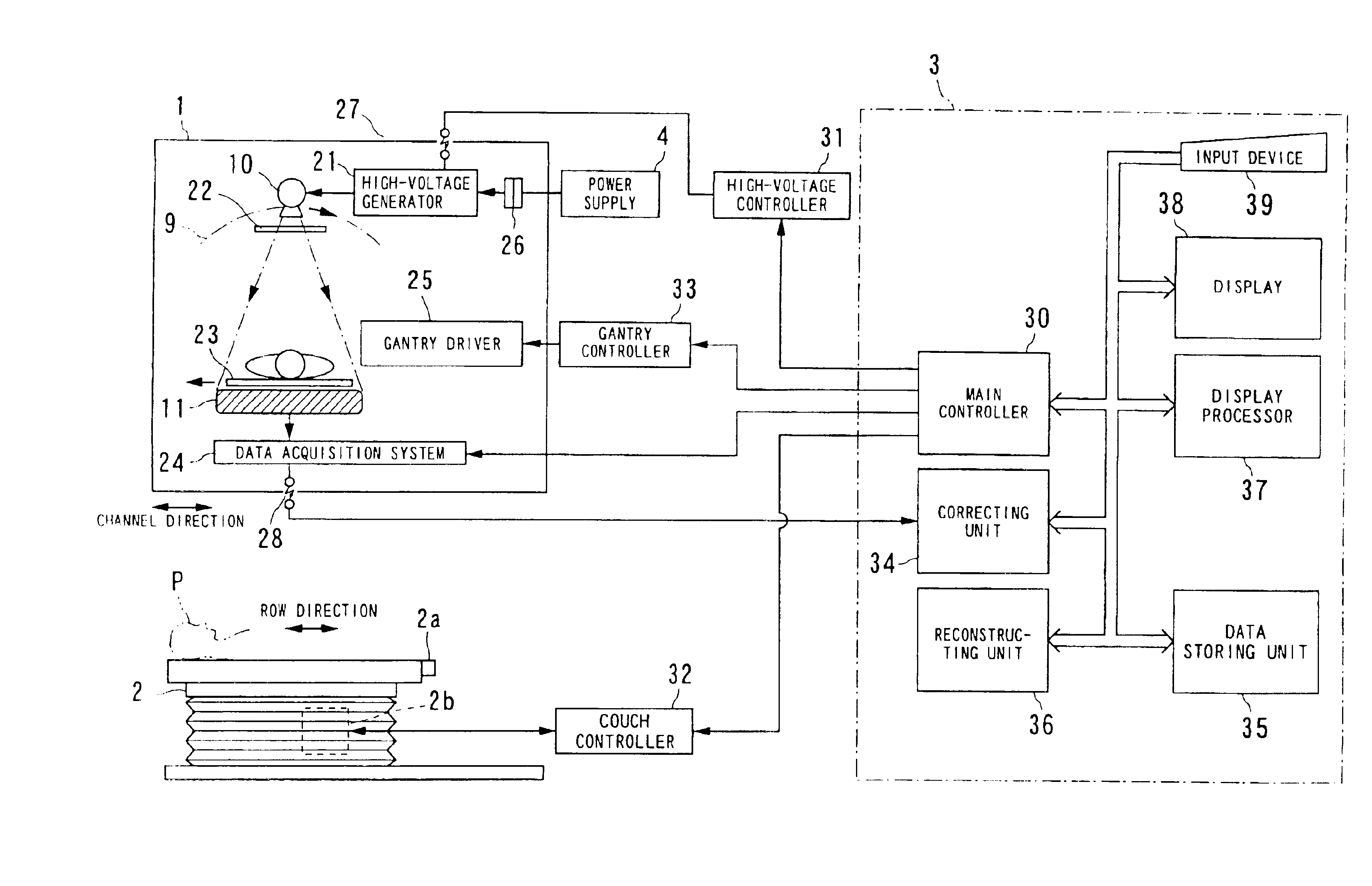
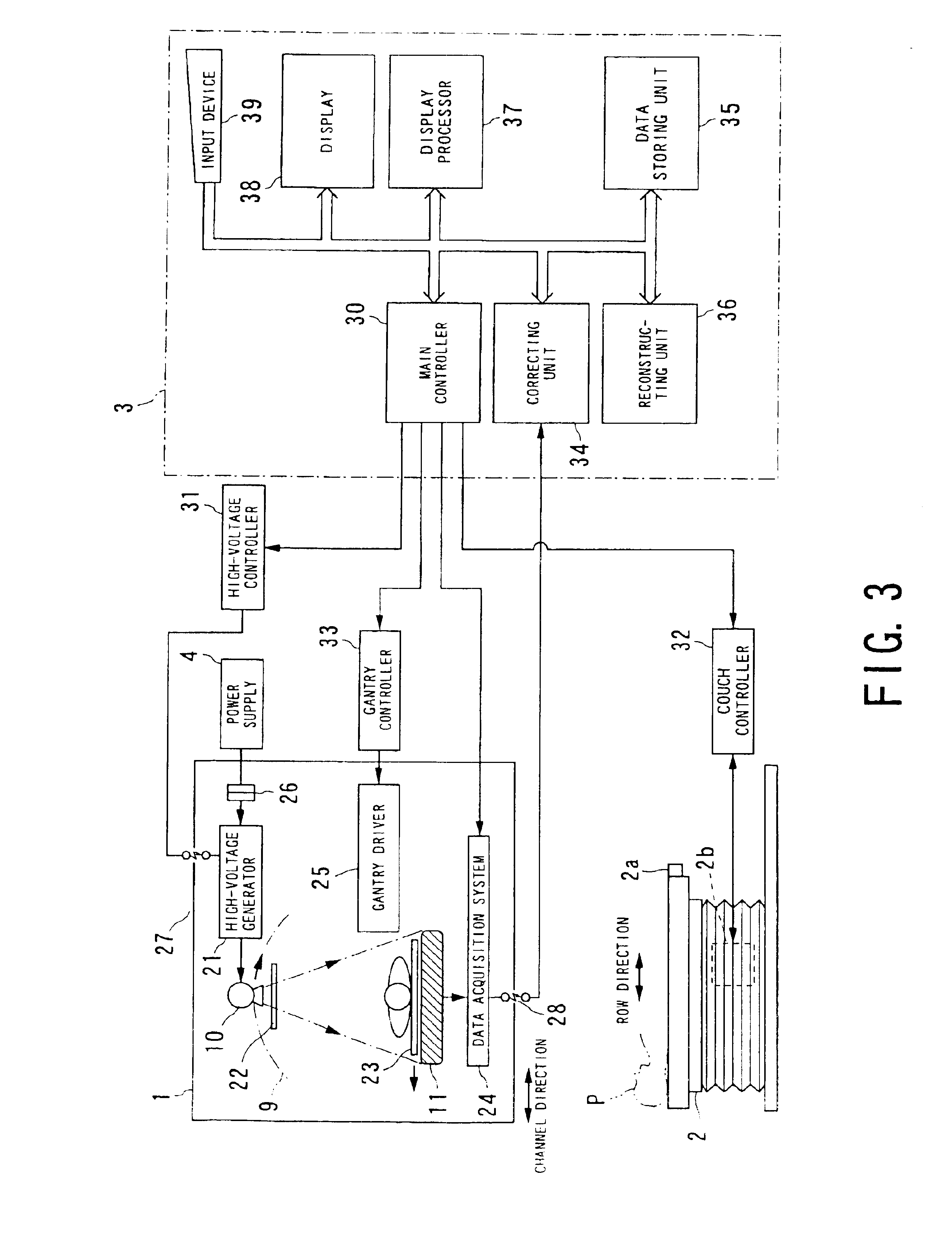
[0058]Referring to FIGS. 1 to 37, an X-ray CT system according to the present invention will now be described. A three-dimensional reconstruction algorithm for X-ray CT and a method of setting a correction function for the X-ray CT according to the present invention will now be described in the explanation of the X-ray CT system, because they are practiced together with the functions of the X-ray CT system.

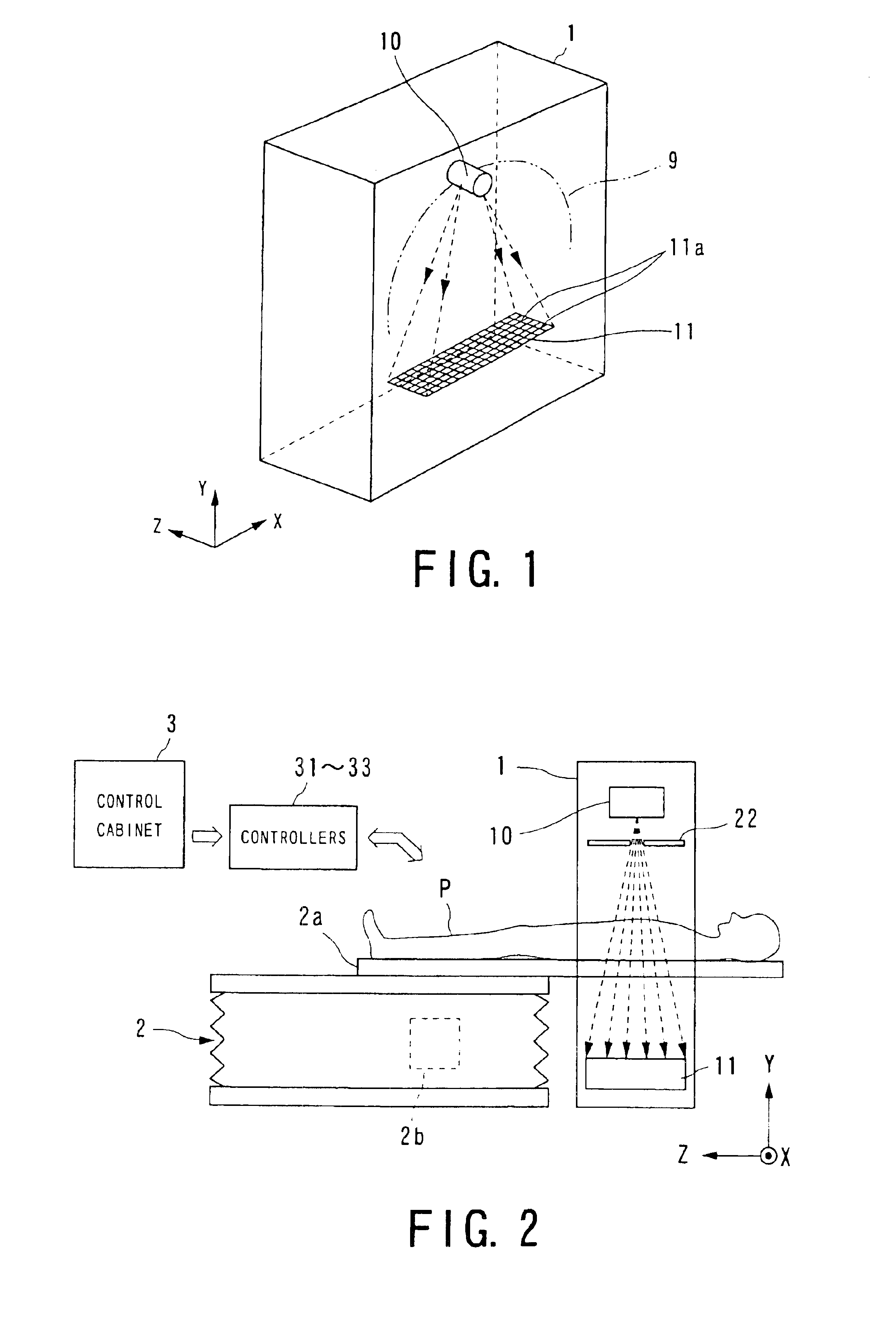
[0059]An X-ray CT scanner (i.e., X-ray CT system) shown in FIGS. 1 to 3 is provided with a gantry 1, a couch 2, a control cabinet 3, a power supply 4, and various controllers and is driven, for example, in an R-R drive manner. The various types of controllers include a high-voltage controller 31, a gantry controller 33, and a couch controller 32.

[0060]As shown in FIGS. 1 and 2, the longitudinal direction of the couch 2 is designated as a low direction Z (or rotation-axis direction or slice direction) and the two directions orthogonal to this direction Z are defined as a channel di...


PUM


Abstract

An X-ray CT system is equipped with a gantry, couch and control cabinet and configured to scan a cone-beam X-ray toward an object along a given orbit to acquire cone-beam data in which a three-dimensional distribution of an X-ray absorption coefficient within the object is reflected. The control cabinet decides a degree of reliability for the cone-beam data according to an acquisition time of the cone-beam data, and then decides a weight for three-dimensional Radon data from the cone-beam data on the basis of the degree of reliability. Using this weight, the control cabinet reconstructs the three-dimensional Radon data based on a three-dimensional reconstruction algorithm. Thus, when the three-dimensional reconstruction algorithm for cone-beam CT is applied to medical CT, artifacts attributable to object's motion can be suppressed and temporal resolution can be improved.

Description

BACKGROUND OF THE INVENTION[0001]1. Technical Field of the Invention[0002]The present invention relates to an X-ray CT system for performing a scan using an cone-like X-ray beam, and in particular, to an X-ray CT system, which is also called cone-beam CT system, that is able to acquire two-dimensional projection data of transmitted X-rays using a two-dimensional detector and obtain CT images by applying three-dimensional reconstruction to the two-dimensional projection data.[0003]2. Related Art[0004]An X-ray CT scanner is provided a gantry in which both of an X-ray tube (X-ray radiation device) and an X-ray detector are disposed to make an object locate therebetween. For example, when an R-R driving technique is adopted, both the X-ray tube and the X-ray detector are driven in synchronism with each other to be rotated about the object, and X-ray beams radiated from the X-ray tube are made to enter the X-ray detector through the object. A DAS (data acquisition system) is connected to...

Claims


Application Information

Patent Timeline
Patent Type & Authority Patents(United States)
IPC IPC(8): A61B6/03G06T11/00
CPCA61B6/032A61B6/4085A61B6/5264A61B6/027G06T11/005Y10S378/901G06T2211/412
Inventor TAGUCHI, KATSUYUKI
Owner KK TOSHIBA
Why Eureka
Try Eureka