
High-tension steel with excellent weldability and plastic deformation ability

A cold forming and steel technology, applied in the direction of building elements, slender elements, etc., can solve the problems of high yield ratio and inaccessibility

Active Publication Date: 2008-09-24
KOBE STEEL LTD
View PDF2 Cites 17 Cited by
  • Summary
  • Abstract
  • Description
  • Claims
  • Application Information

AI Technical Summary

Problems solved by technology

In this technique, a steel sheet (thickness: 80mm) containing Mo and having a carbon equivalent Ceq of about 0.45% is subjected to quenching (Q)-two-phase domain quenching (Q': about 780°C)-tempering (T) to obtain Composite structure consisting mainly of ferrite and bainite, but the yield ratio is relatively high (maximum: 80%, average: 77.4%), and the target 75% or less cannot be obtained

Method used


Image

  • High-tension steel with excellent weldability and plastic deformation ability
  • High-tension steel with excellent weldability and plastic deformation ability
  • High-tension steel with excellent weldability and plastic deformation ability

Examples


Embodiment 1

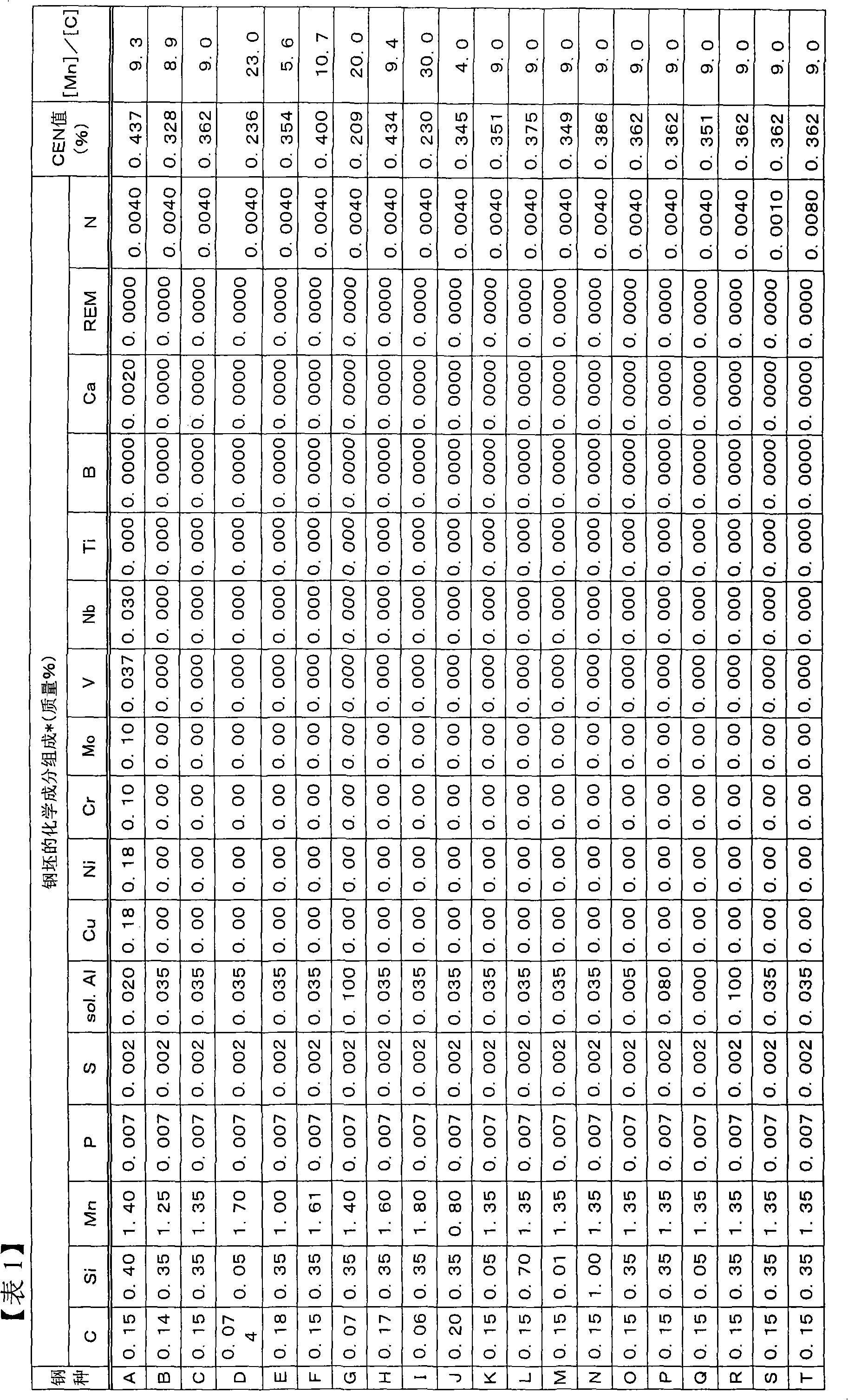
[0092] Steels with the chemical compositions shown in Tables 1 and 2 below were smelted according to common smelting methods to form steel slabs, and then any one of the treatments (types 1 to 5) shown below was performed to manufacture steel sheets. In addition, Tables 1 and 2 also show the value of CEN and the value of [Mn] / [C] defined by the above formula (1). The production conditions at this time are shown in Tables 3 and 4 below.

[0093] (processing steps)

[0094] Type 1: After performing controlled rolling (CR), normalizing (N) was performed (test No. 1 described later). The normalizing (N) here is from Ac 1 Air cooling at temperatures above the phase transition point.

[0095] Type 2: Accelerated cooling was performed after controlled rolling (test No. 2 described later).

[0096] Type 3: Controlled rolling (CR), followed by normalizing (N), followed by quenching (Q') at the dual-phase temperature (test No. 3 described later).

[0097] Type 4: After controlled r...

Embodiment 2

[0140] Steels with the chemical compositions shown in Tables 9 and 10 below were smelted according to common smelting methods to form steel slabs, and then any one of the treatments (types 1 to 5) shown below was performed to manufacture steel sheets. In addition, Tables 1 and 2 also show the value of CEN and the value of [Mn] / [C] defined by the above formula (1). The manufacturing conditions at this time are shown in Tables 11 and 12 below.

[0141] (processing steps)

[0142] Type 1: Normalizing (N) was performed after controlled rolling (CR) (test No. 44 described later). The normalizing (N) here is from Ac 1 Air cooling at temperatures above the phase transition point.

[0143] Type 2: After controlled rolling, accelerated cooling was performed (Test No. 45 described later).

[0144] Type 3: Controlled rolling (CR), followed by normalizing (N), followed by quenching (Q') at the dual-phase temperature (test No. 46 described later).

[0145] Type 4: After controlled rol...


PUM

PropertyMeasurementUnit
diameteraaaaaaaaaa
tensile strengthaaaaaaaaaa

Abstract

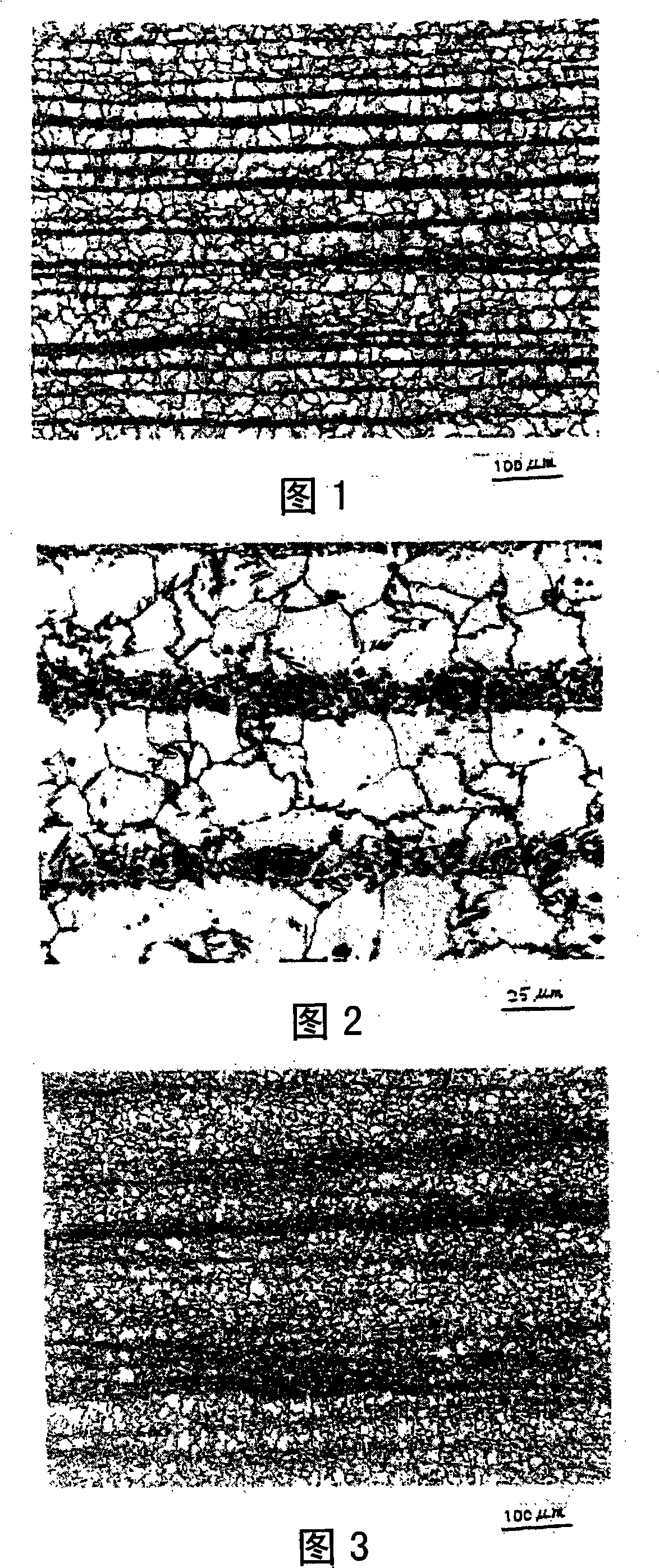
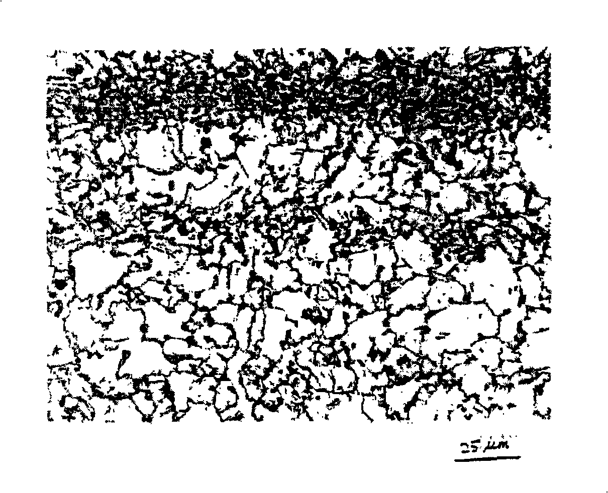
The steel in the invention has specified chemical composition with the CEN valve specified by the following formula (1) in the specified range; the microscopic constitution composition of the steel is 65-85 volume% multilateral ferrite phase, 5-20 volume% strip pearlite phase, 3-15 volume% granulose tempered martensite phase existed in grain boundary ferrite; and the average equivalent circle diameter of the multilateral ferrite phase is 10-40 [mu]m. CEN=[C]+A(c).{[Si] / 24+[Mn] / 6+[Cu] / 15+[Ni] / 20+([Cr]+[Mo]+[Nb]+[V]) / 5}...(1); wherein, A(c)=0.75+0.25.tanh{20[C] -0.12}, [C], [Si], [Mn], [Cu], [Ni], [Cr], [Mo], [Nb] and [V] respectively represent content (mass%) of C, Si, Mn, Cu, Ni, Cr, Mo, Nb and V. According to the composition, like suiting for cold-forming round steel pipe, although the steel plate is exerted on strong processing (bending processing, tensile processing, compressing processing etc.) and does not execute SR processing, the tensile ratio is stable below 85% and has excellent toughness and weldability to be high-tension steel with tensile strength above 490 MPa.

Description

technical field [0001] The present invention relates to a high-tensile steel material having a tensile strength of 490 MPa or more at a low yield ratio with excellent weldability, and a cold-formed steel pipe obtained from the steel material, and particularly relates to a CFT (Concrete-Filled Tube) that can be applied to a CFT (Concrete-Filled Tube) that is excellent in shock resistance The structure of the building is 490MPa as well as high-tensile steel and cold-formed steel pipes. Background technique [0002] According to the revision of the New Seismic Design Law (1981), the plastic deformation of steel is allowed during a major earthquake in the construction field, and the energy of the earthquake is absorbed to prevent the collapse of the building. This design concept is centrally incorporated into high-rise buildings, so as The required properties of steel require a low yield-to-strength ratio. [0003] In building structures, excellent earthquake resistance and fir...

Claims


Application Information

Patent Timeline
Patent Type & Authority Applications(China)
IPC IPC(8): C22C38/06C22C38/48C22C38/58C21D1/18C21D8/10F16S3/00
CPCC21D2211/005C22C38/001C22C38/02C22C38/04C22C38/06
Inventor 柴田光明
Owner KOBE STEEL LTD
Learn More