Method and device for charging processing plants

A processing equipment and charging technology, which is applied in combustion methods, combustion equipment, solid fuel pretreatment, etc., can solve problems such as blockage of conveying pipelines, inability to ensure, and long service time, and achieve the effect of simple structure

Inactive Publication Date: 2008-09-24
库尔特·希姆尔弗洛恩德波茵特纳
View PDF0 Cites 1 Cited by
  • Summary
  • Abstract
  • Description
  • Claims
  • Application Information

AI Technical Summary

Problems solved by technology

This often leads to clogging of conveying pipes, especially when materials are conveyed under pressure
Therefore, when handling the

Method used


Image

  • Method and device for charging processing plants
  • Method and device for charging processing plants
  • Method and device for charging processing plants

Examples


Embodiment Construction

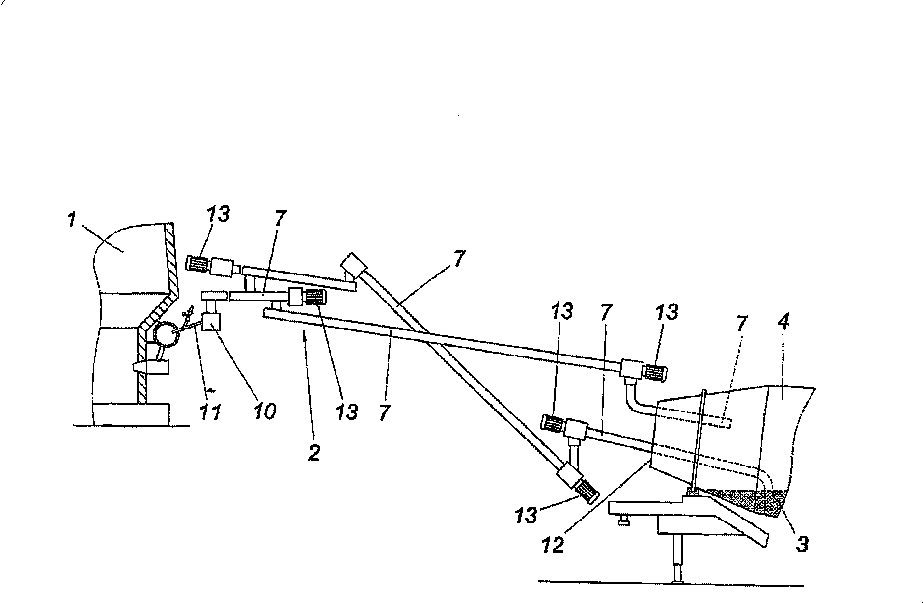
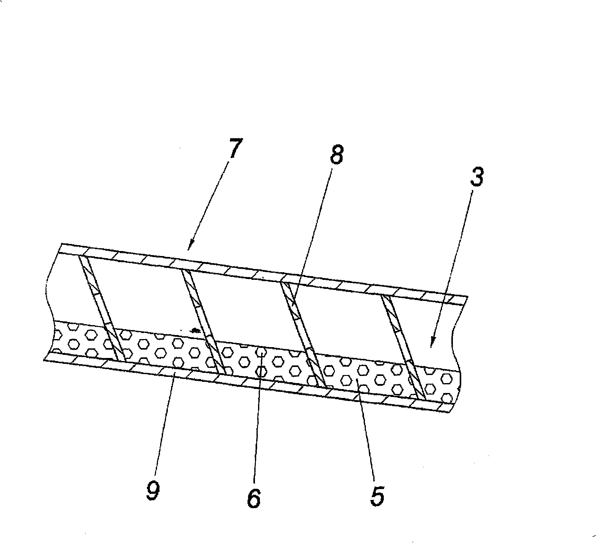
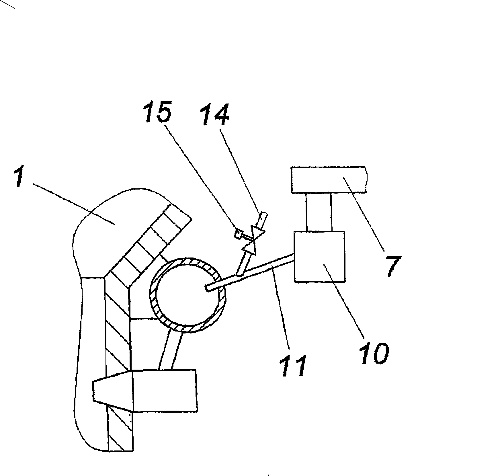
[0018] figure 1 The charging device shown by way of example for a treatment plant designed as a combustion furnace 1 has a delivery line 2 with which flowable treatment material 3 is received and charged into the combustion furnace 1 . The conveying line 2 draws the process material 3 from a mixer constituted as a drum mixer 4, which is responsible for continuously supplying the conveying line 2 with the process material 3, wherein a liquid part 5 is mixed with a solid part 6, in particular The solid part 6 is distributed almost evenly in the liquid part 5, which can be referred to in particular figure 2 . This flowable process material 3 can be, for example, a mixture of oil or sludge with plastics, metals and / or silicates.

[0019] From figure 2 It can be seen that in this section the conveying line 2 , which is formed as a screw conveyor 7 , is used for pressure-free conveying of the process material 3 . However, it is also conceivable to use a pump-pressurized convey...


PUM


Abstract

A device and method for charging processing plants, in particular, combustion furnaces (1), is disclosed, in which a flowing process material (3), which has solid components (6) in addition to liquid components (5), is introduced into the processing plant (1), by means of a conveyor line (2) under pressure. According to the invention, advantageous charging conditions may be achieved, by means of mixing the process material (3) before pressurisation.

Description

technical field [0001] The invention relates to a charging device and method for a treatment plant, in particular a combustion furnace, in which a flowable treatment material having a solid part in addition to a liquid part is charged into the treatment plant through a conveying line under pressure. Background technique [0002] In order to be able to transport the solid treatment material to the treatment equipment constituted as a combustion furnace, so that the treatment material is not completely or partially carried away by the rising hot gas when it is not burned, it is known to feed the solid treatment material and the liquid treatment material into the combustion furnace. The current situation shows that it is precisely this flowable process material containing solid and liquid parts that is difficult to convey, since the solid part is easily separated from the liquid part. This often leads to clogging of conveying pipes, which occurs especially when handling materia...

Claims


Application Information

Patent Timeline
IPC IPC(8): F23K1/02F23K5/04
CPCF23K2201/501F23K1/02F23K5/04F23K2201/503F23K2203/202F23K2300/103F23K2300/201
Inventor 库尔特·希姆尔弗洛恩德波茵特纳
Owner 库尔特·希姆尔弗洛恩德波茵特纳
Why Eureka
Try Eureka