Surveying device and surveying method

A measuring device and a technology for measuring pulses, which are applied in measuring devices, active optical measuring devices, measuring distances, etc., can solve the problems of insufficient high-precision measurement and the inability to eliminate measurement errors, and achieve the effect of small measurement errors

Inactive Publication Date: 2008-09-24
KK TOPCON
View PDF1 Cites 17 Cited by
  • Summary
  • Abstract
  • Description
  • Claims
  • Application Information

AI Technical Summary

Problems solved by technology

[0004] However, in the case of conventional devices, although the attenuated oscillation waveform of the received optical signal can be used to reduce the influence

Method used


Image

  • Surveying device and surveying method
  • Surveying device and surveying method
  • Surveying device and surveying method

Examples


Embodiment Construction

[0085] Embodiments of the present invention will be described below with reference to the drawings.

[0086] In the embodiment, a measurement device and a measurement method will be described. The measurement device uses a light-emitting element (pulsed laser diode: PLD) as a light source, reflects the measurement pulse light irradiated from the light source by the object to be measured, and detects the reflection. The time required for the light to return is measured by measuring the delay time (required time difference) between the measurement pulse light and the reference pulse light or the distance to the measurement object, and is measured using TOF (Time of Flight).

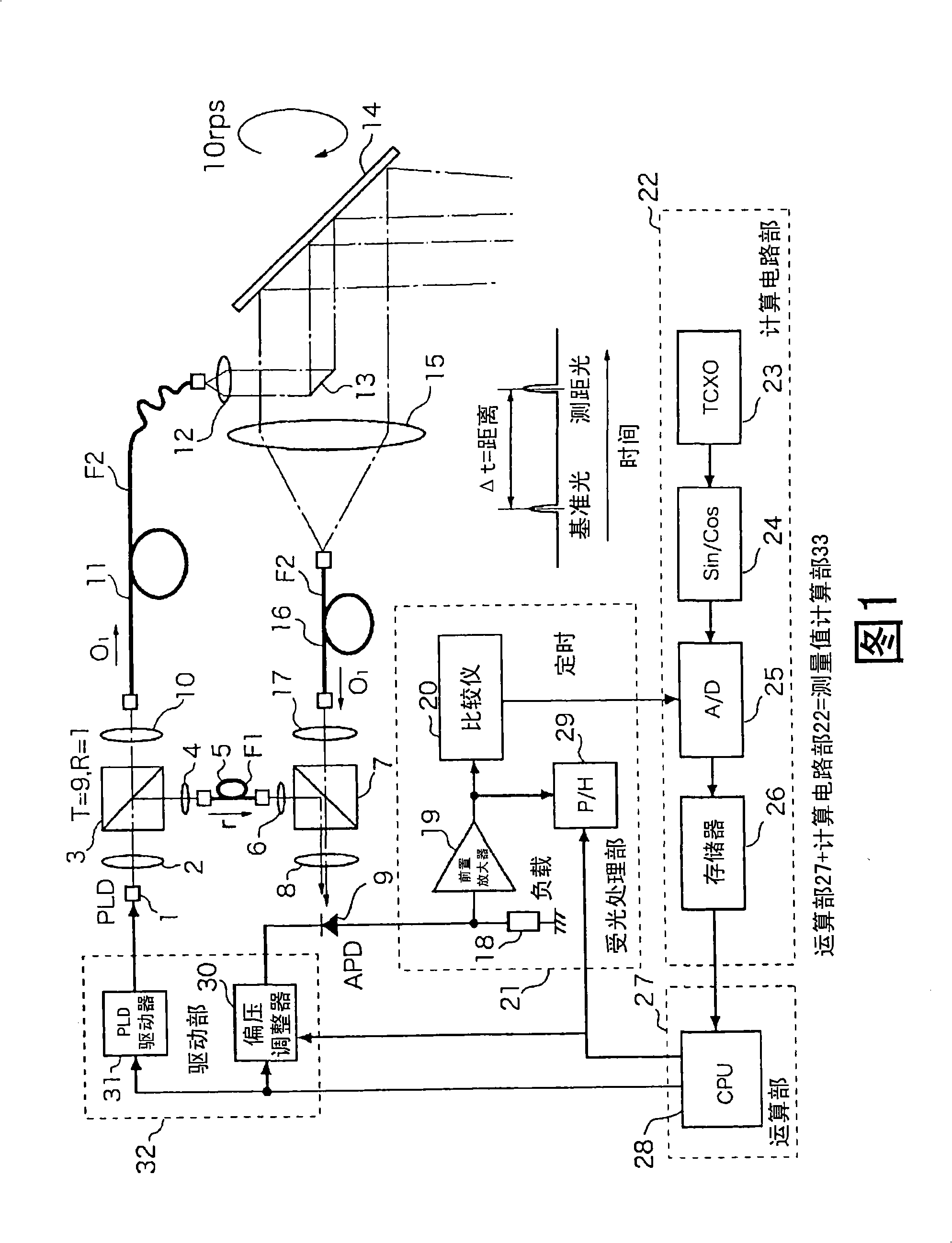
[0087] FIG. 1 is a block diagram showing a configuration example of a device in the first embodiment of the present invention.

[0088] The light beam from the PLD1 as a light emitting element passes through the collimator lens 2 to become a parallel beam, and then enters the beam splitter 3 to split into a...


PUM


Abstract

A surveying device and method for measuring the delay time or distance with a smaller measurement error by directing a light beam to an object to be measured and receiving the reflected light beam. A reference pulse light (r) and a measurement pulse light (o1) are received as light reception signals by a light-receiving section (9). A damping signal (S3U) is generated from the light reception signals (r, o1). The gain of the signal of minute level near the zero-cross point (Q0) of the damping signal (S3U) is made high to amplify the signal with the high gain. Timing signals (r', O1') are generated using the amplified signal. With this, the measurement error can be minute.

Description

technical field [0001] The invention relates to a measuring device and a measuring method. Specifically, it relates to a measurement device and a measurement method for measuring delay time or distance by irradiating light to a measurement object and receiving reflected light. Background technique [0002] Conventionally, there is a device that amplifies and receives reflected light reflected from a measurement object such as a target by a photomultiplier tube or an avalanche photodiode (APD), performs predetermined processing, and measures delay time or distance. In this device, light with a wide range of levels from strongly reflected light from a short distance to slightly reflected light from a long distance is obtained, and in this case, since a change in the intensity of the received light signal tends to appear as a measurement error, the A device is proposed that detects and amplifies the zero-crossing point of a damped signal obtained by extracting a part of its fr...

Claims


Application Information

Patent Timeline
IPC IPC(8): G01S17/10G01C3/06G01C15/00G01S7/486
CPCG01C15/002G01S7/497G01S7/4818G01S17/10G01S7/486
Inventor 大石政裕峰岸功
Owner KK TOPCON
Why Eureka
Try Eureka