Non-nozzle continuous electrostatic spinning system

An electrospinning, no-nozzle technology, used in textiles and papermaking, filament/thread forming, fiber processing, etc., can solve the problems of small diameter of the nozzle, difficult to clean, difficult to increase the output, etc., to achieve high quality and avoid electric fields. Interference, efficiency improvement effect

Inactive Publication Date: 2008-10-01
SOUTH CHINA UNIV OF TECH
View PDF0 Cites 34 Cited by
  • Summary
  • Abstract
  • Description
  • Claims
  • Application Information

AI Technical Summary

Problems solved by technology

[0002] Electrospinning, as a novel and convenient technology for forming micro- and nanofibers, has been paid more and more attention. At present, most electrospinning equipment adopts the method of single nozzle, multiple nozzles, rotating nozzles or composite nozzles, but whether it is single Nozzles, multi-nozzles, rotary nozzles, composite nozzles, due to the s

Method used


Image

  • Non-nozzle continuous electrostatic spinning system
  • Non-nozzle continuous electrostatic spinning system
  • Non-nozzle continuous electrostatic spinning system

Examples


Embodiment 1

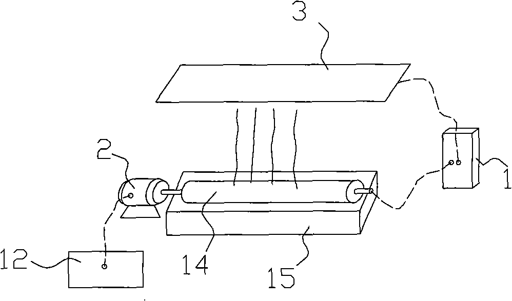
[0024] Such as figure 1 As shown, a continuous electrospinning system without a nozzle, the system includes a liquid supply device, a rotating assembly, a receiving device 3 and an electrostatic generator 1, the liquid supply device supplies liquid to the rotating assembly, and the rotating assembly is connected to the driving device 2 by transmission. The receiving device 3 is opposite to the rotating assembly, one pole of the electrostatic generator 1 is electrically connected to the receiving device 3, and the other pole is electrically connected to at least one of the liquid supply device and the rotating assembly.

[0025] In this embodiment, the liquid supply device is a liquid collection tank 15, the rotating component is a rotating roller 14, the driving device 2 is a frequency conversion motor, and the frequency conversion motor is electrically connected to the control circuit 12, and the receiving device 3 is a receiving plate; the rotating roller 14 is driving Under...

Embodiment 2

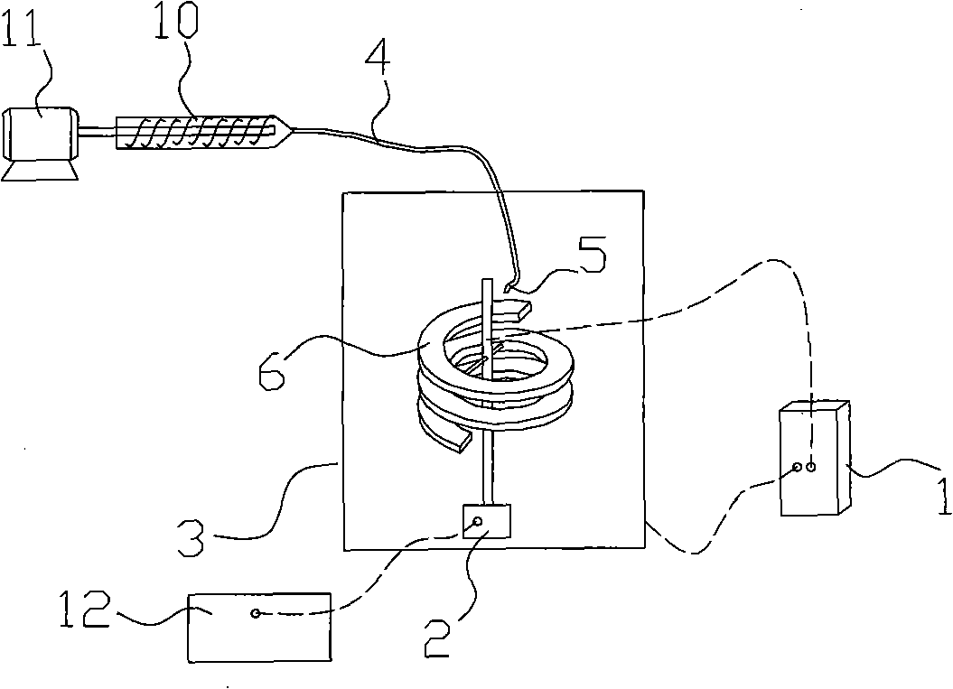
[0027] Such as figure 2 As shown, in the present embodiment, the liquid supply device includes a liquid supply pipe 4 and an extrusion mechanism. The extrusion mechanism is a screw propeller 10. The pipe 4 is connected; the rotating assembly is a spiral liquid collecting plate 6, the axis of the spiral liquid collecting plate 6 is the center of rotation, the liquid outlet 5 of the liquid supply pipe 4 is located above the liquid collecting plate 6, and the receiving device 3 is Cylindrical, and opposite to the edge of the spiral liquid collecting plate 6.

[0028] The effect of this embodiment is better than that of Embodiment 1. During the working process, under the action of the motor 11, the screw propeller 10 feeds the spinning liquid into the liquid supply pipe 4, and the spinning liquid flows from the liquid outlet 5 to the spiral On the liquid collecting plate 6, the liquid collecting plate 6 rotates at a high speed under the action of the driving device 2 and throws ...

Embodiment 3

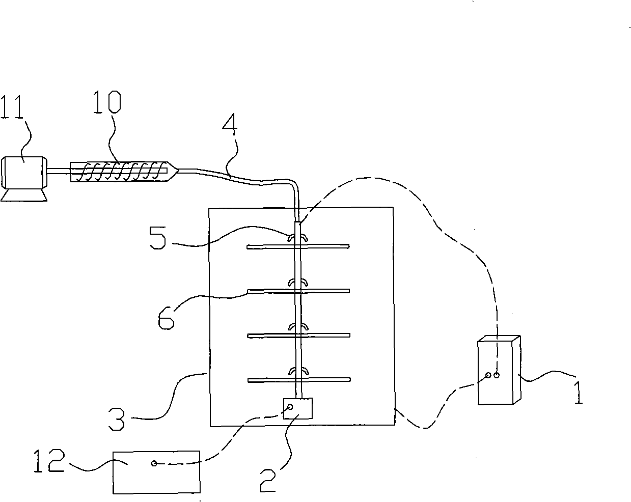
[0030] Such as image 3 , Figure 4 As shown, in the present embodiment, the liquid collecting plate 6 is a circular plate, the axis of the circular plate is the center of rotation, and there are four liquid collecting plates 6 arranged in layers along the upper and lower directions, and the top of each liquid collecting plate 6 is A liquid outlet 5 is provided. Depend on Figure 4 It can be seen that after the spinning solution 13 flows to the liquid collecting plate 6, it flows to the edge of the liquid collecting plate 6 under the action of centrifugal force and is distributed in a star shape on the liquid collecting plate 6. The principle of this embodiment is the same as that of the second embodiment. I won't repeat them here.


PUM


Abstract

The invention discloses a non showerhead continuously electrostatic spinning system, which includes a liquid feeding apparatus, a rotating component, a receiving apparatus and an electrostatic generator, wherein, the liquid feeding apparatus provides liquid for the rotating component, the rotating component is connected to a driving mechanism in transmission, the receiving apparatus faces to the rotating component, one pole of the electrostatic generator is electrically connected to the receiving apparatus, and the other pole is electrically connected to at lest one of the liquid feeding apparatus and the rotating component. The inventive spinning system has good product quality and high efficiency.

Description

technical field [0001] The invention relates to a nozzleless continuous electrostatic spinning system. Background technique [0002] Electrospinning, as a novel and convenient technology for forming micron and nanofibers, has been paid more and more attention. At present, most electrospinning equipment adopts the method of single nozzle, multiple nozzles, rotating nozzles or composite nozzles, but whether it is a single nozzle Nozzles, multi-nozzles, rotary nozzles, composite nozzles, due to the small diameter of the nozzles, there are problems such as difficult to clean and difficult to increase the output, especially for the method of multi-nozzles, the electric field interference between adjacent nozzles cannot be effective The avoidance of it affects the uniformity of mass fiber production, and the quality and efficiency of fiber production need to be improved. Contents of the invention [0003] The object of the present invention is to provide a nozzleless continuous...

Claims


Application Information

Patent Timeline
IPC IPC(8): D01D5/00
Inventor 严玉蓉卓坚锐李诗丞陈麒阮镜棠张振斌温焯维赵耀明
Owner SOUTH CHINA UNIV OF TECH
Why Eureka
Try Eureka