Pipe joint
A technology of pipe joints and pipe bodies, applied in the field of pipe joints, can solve the problems of large amount of use, inability to stop water, and inability to exert water-stopping functions.
- Summary
- Abstract
- Description
- Claims
- Application Information
AI Technical Summary
Problems solved by technology
Method used
Image

Examples
Embodiment 1
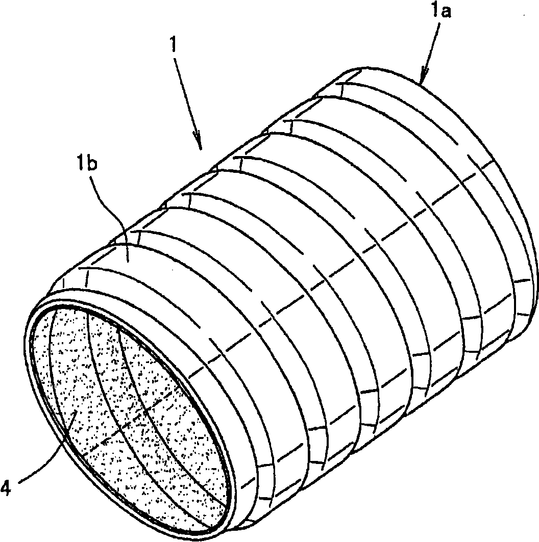
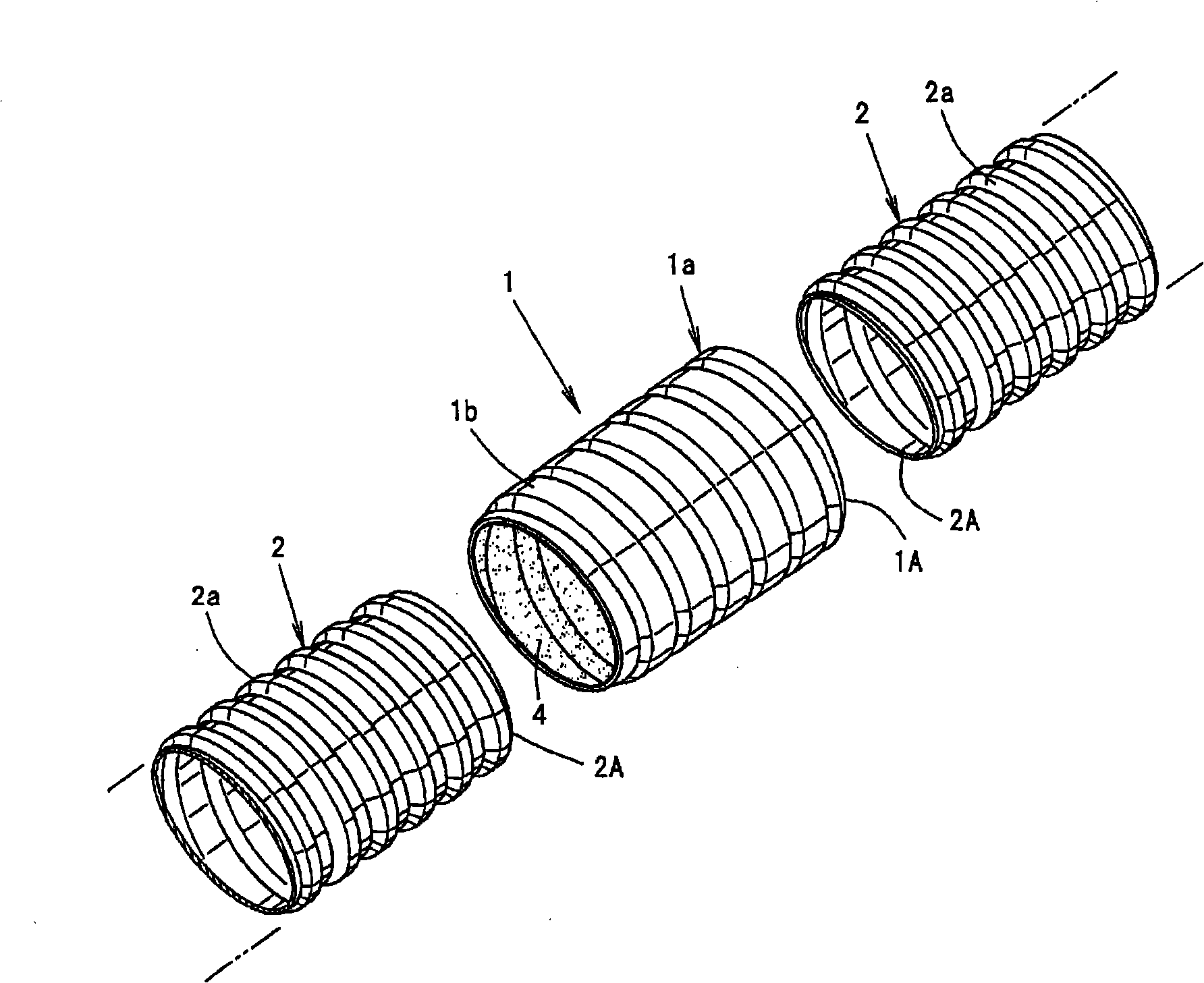
[0141] figure 1 , figure 2 The pipe joint 1 of Embodiment 1 is shown. The pipe joint 1 is formed by expanding layered or sheet-like water over the entire area of the inner peripheral surface of a joint body 1a made of synthetic resin or synthetic rubber with continuous spiral grooves 1b. The part 4 is integrated, and connects one pipe body 2 (so-called pipe) having spiral concavo-convex strips 2a and the other pipe body 2 (so-called pipe) having spiral concavo-convex strips 2a.
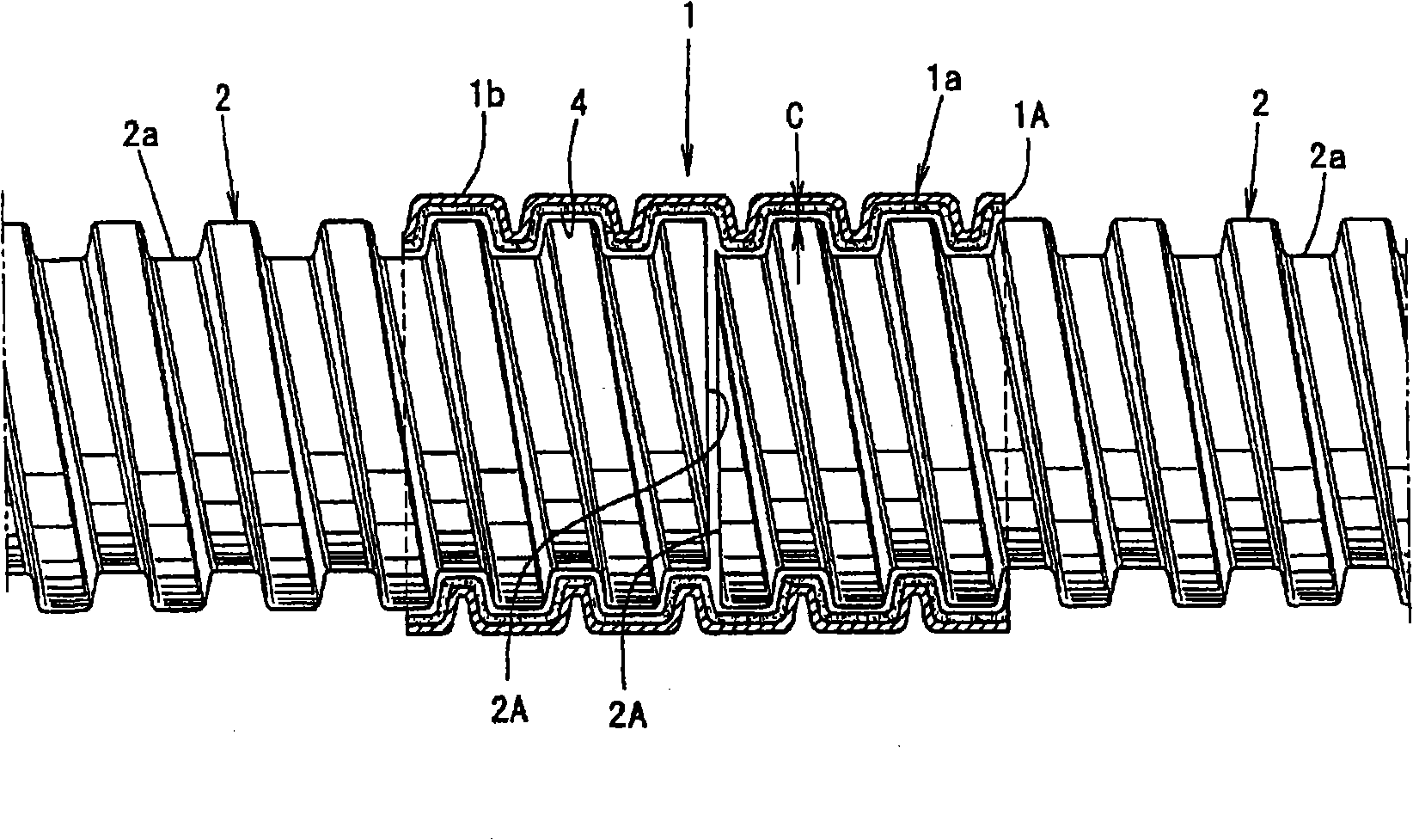
[0142] That is, the pipe joint 1 is sleeved on the pipe body 2 and connected until the other end 1A of the pipe joint 1 coincides with the end 2A of the one pipe body 2, and then the end 2A of the pipe body 2 is aligned with the other end 2A. After the end 2A of the pipe body 2 is the same or roughly the same, the pipe joint 1 that has been screwed in is unscrewed by about half of the screw-in amount, and the other side of the pipe joint 1 is sleeved on the pipe body 2 to connect, such as image 3 As...
Embodiment 2
[0171] Figure 8 The pipe joint 1 of Embodiment 2 is shown. The pipe joint 1 is made of synthetic resin or rubber with continuous spiral concave and convex strips 1b composed of a convex portion 1bA protruding inward in the radial direction and a concave portion 1bB forming an outer peripheral portion. The inner peripheral surface of the joint body 1a is integrally formed by integrating a water swelling portion 4 of substantially uniform thickness, which will have Figure 8 The shown top 2aA and valley 2a constituted by the spiral concave-convex strip 2a one side of the tube 2 (the so-called tube) and the top 2aA and the valley 2a constituted by the spiral concave-convex strip 2a on the other side of the tube 2 (the so-called的管) Connect in the same way as in the first embodiment above.
[0172] Picture 9 , Picture 10 In this case, the number of helical protrusions in the axial direction of the joint body 1a, that is, the number of protrusions 1bA is "4-6". As an example, the c...
Embodiment 3
[0198] Figure 23 The pipe joint 1 of Embodiment 3 is shown. The pipe joint 1 connects the pipe bodies 2 and 2 made of synthetic resin in the same manner as the above-mentioned Embodiment 1 and Embodiment 2, and has the pipe bodies connected by screwing on both sides In the cylindrical shape of the connecting portion 1c at the two ends, a water-stopping function layer 3 that absorbs water and expands is formed on the inner surface of the joint body 1a having the spiral concave-convex strips 1b to stop water between the pipe bodies 2 after the connection. In the pipe joint 1 of this example, the entire longitudinal direction has the same shape as the connecting portion 1c.
[0199] The water-stop function layer 3 is formed using a water-swellable portion 4 made of a water-swellable nonwoven fabric. Figure 24 It is an explanatory diagram showing the structure of the water-stopping functional layer 3. The water-stopping functional layer 3 is formed by providing a holding clip 5 mad...
PUM
| Property | Measurement | Unit |
|---|---|---|
| Softening point | aaaaa | aaaaa |
| Softening point | aaaaa | aaaaa |
Abstract
Description
Claims
Application Information
 - R&D Engineer
- R&D Manager
- IP Professional
- Industry Leading Data Capabilities
- Powerful AI technology
- Patent DNA Extraction
Browse by: Latest US Patents, China's latest patents, Technical Efficacy Thesaurus, Application Domain, Technology Topic.
© 2024 PatSnap. All rights reserved.Legal|Privacy policy|Modern Slavery Act Transparency Statement|Sitemap