Socket type LED apparatus

An LED device, a socket-type technology, applied to coupling devices, lighting devices, components of lighting devices, etc., can solve problems such as damage to LED chips, damage to peripheral components, etc., to achieve the effect of convenient replacement and enhanced heat dissipation

Inactive Publication Date: 2008-10-01
EVERLIGHT ELECTRONICS
View PDF0 Cites 1 Cited by
  • Summary
  • Abstract
  • Description
  • Claims
  • Application Information

AI Technical Summary

Problems solved by technology

[0005] The purpose of the present invention is to provide a socket-type LED device combined with an LED module. Compared with the existing method of electrical bonding by soldering, it can solve the problem that the LED chip is damaged due to heat during the welding process and the high temperature in the desoldering step The problem of causing damage to peripheral components, and the socket structure combined with the heat dissipation mechanism in the socket-type LED device can be applied to the LED device to improve the effect of heat dissipation

Method used


Image

  • Socket type LED apparatus
  • Socket type LED apparatus
  • Socket type LED apparatus

Examples


Embodiment Construction

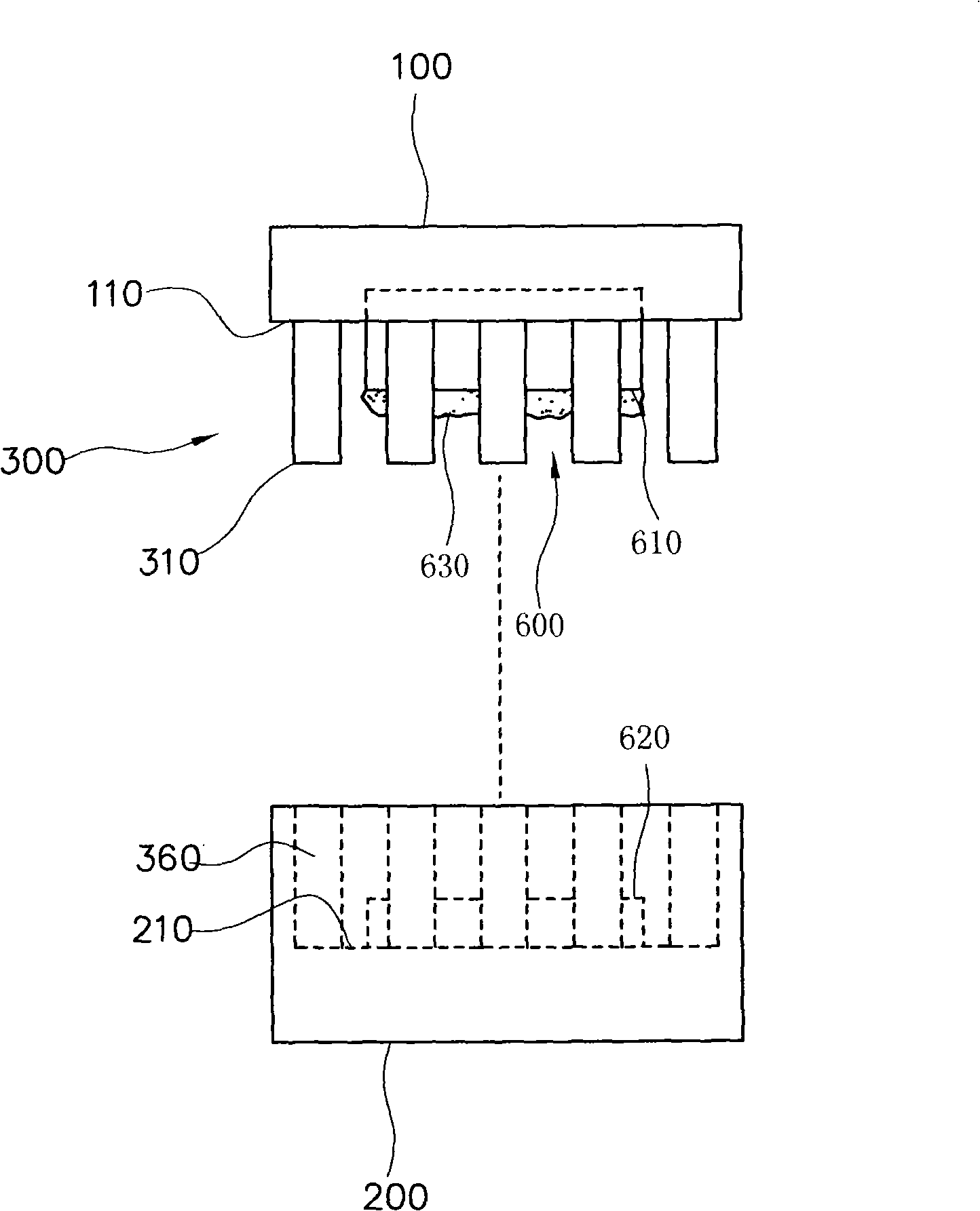
[0028] Please refer to figure 1 , is a schematic diagram of the side structure of a heat dissipation socket according to an embodiment of the present invention. The heat dissipation socket of this embodiment includes a first seat body 100, a second seat body 200, a conductive device 300, and a heat dissipation device 600. This heat dissipation socket can be a PLCC (Plastic Leaded Chip Carrier, PLCC, plastic led foot chip carrier) socket.

[0029] The first base body 100 is made of insulating material such as plastic or ceramics, and includes a first abutting surface 110 . The second seat body 200 is also made of insulating material such as plastic or ceramics and is detachably disposed on the first seat body 100 , and includes a second mating surface 210 corresponding to the first mating surface 110 . The heat dissipation device 600 is disposed between the first base body 100 and the second base body 200, wherein the heat dissipation device 600 can be an integrally formed he...


PUM


Abstract

The invention discloses a jack type LED device, including a first seat, a second seat, an electric installation, a heat sink and an LED module, wherein the first seat can be inserted on the second seat, the heat sink can be arranged between the first seat and the second seat. The electric installation includes two condition pins and two condition slots respectively arranged on the first and the second butting surface. The LED module is arranged on the first seat, having a condition basis material with one side sticked with the heat sink and a condition part electrically connected with the condition pins. The alternated radiators can make the heat energy reduced descendingly to reach the better heat emission effect.

Description

technical field [0001] The invention relates to a socket-type LED device combined with an LED (light-emitting diode) module, in particular to a socket-type LED device combined with a heat dissipation mechanism. Background technique [0002] Most of the existing electronic components need to be joined with the circuit board by soldering. Since the soldering temperature is approximately between 350°C and 380°C, under such high temperature operation, electronic components may be damaged due to improper operation and high temperature during soldering. On the other hand, the same problem also exists when the electronic components are replaced for the desoldering operation, which also causes inconvenience in replacing the components and cannot effectively reduce the cost of the product. [0003] In addition, as the power of electronic components increases, the heat generated per unit area also increases rapidly. The existing high-power LEDs are used as illustrations. LEDs are fas...

Claims


Application Information

Patent Timeline
Patent Type & Authority Applications(China)
IPC IPC(8): F21S2/00F21V19/00F21V29/00H01R33/05F21Y101/02F21K9/20F21V29/70F21V29/85F21V29/89F21Y115/10
Inventor 梁家豪锺协志蔡欣璋
Owner EVERLIGHT ELECTRONICS
Why Eureka
Try Eureka