Hair shortening device

An equipment and hair technology, applied in medical science, surgery, parts of surgical instruments, etc., can solve the problems of complexity, reduce energy efficiency, and large total energy of hair, achieve the effect of large degree of freedom and reduce energy consumption

Inactive Publication Date: 2008-10-01
KONINKLIJKE PHILIPS ELECTRONICS NV
View PDF2 Cites 9 Cited by
  • Summary
  • Abstract
  • Description
  • Claims
  • Application Information

AI Technical Summary

Problems solved by technology

[0008] The disadvantage of the device is that the total energy required to damage the hair is relatively large
This not only means reduced energy efficiency, but also makes the laser source and its energy source larger and more complex as a result

Method used


Image

  • Hair shortening device
  • Hair shortening device
  • Hair shortening device

Examples


Embodiment Construction

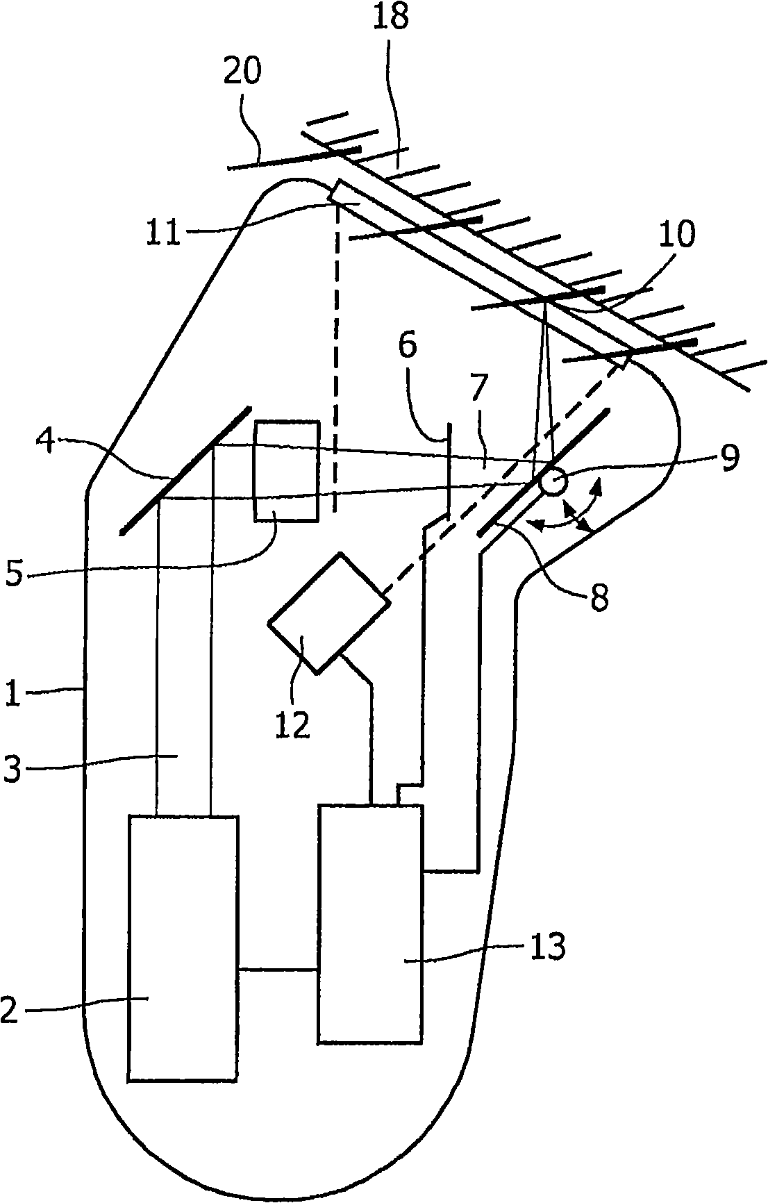
[0048] figure 1 An embodiment of the device according to the invention is shown diagrammatically.

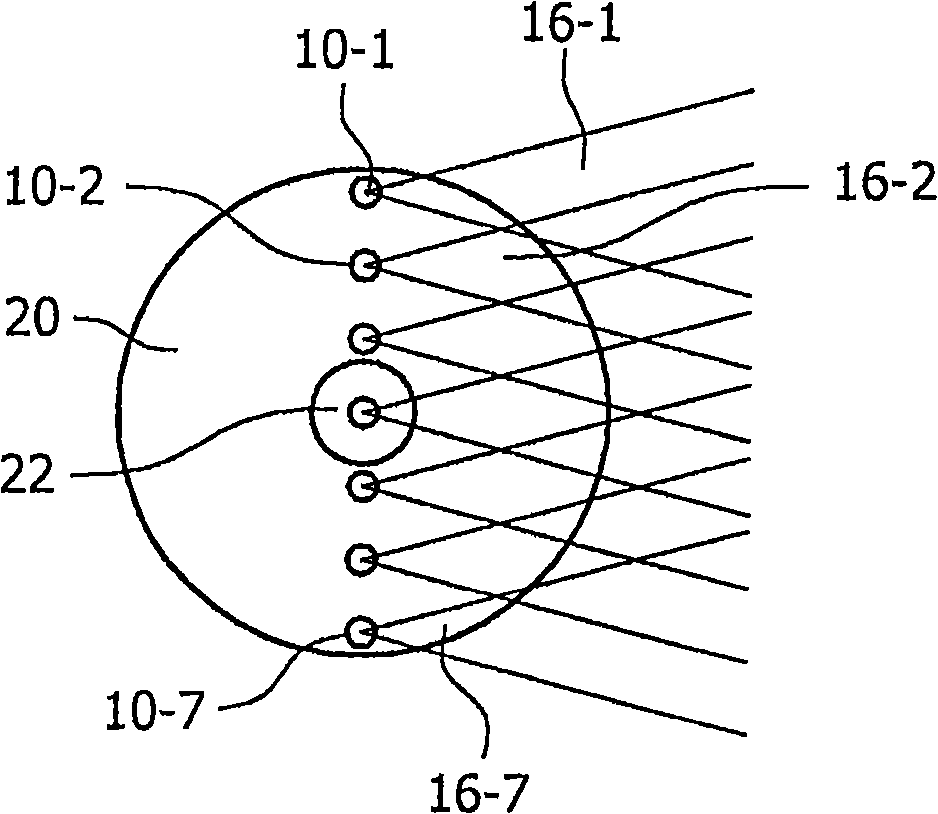
[0049] The device comprises a housing 1 with a laser source 2 emitting a laser beam 3 which is (optionally) reflected by an optional fixed mirror 4 and passes through an optical focusing element 5 and a beam multiplier element 6 to direct the laser beam to The beam is converted into a plurality of focused laser beams 7 (only one shown). A plurality of focused laser beams 7 is reflected by a mirror 8 which is movable about an axis 9 . Each of the plurality of focused laser beams forms a focal point 10 and exits the housing 1 through an optical window 11 .

[0050] Reference numeral 12 denotes a CCD camera connected to a control unit 13 which is also connected to the laser source 2 and the mirror 8 .

[0051] Also, reference numeral 18 denotes skin, which has many hairs 20 .

[0052] Housing 1 may be any type of housing suitable for the part. The housing can be made of any d...


PUM


Abstract

The invention relates to a hair-shortening device. The device is based on the principle of laser- induced optical breakdown, wherein a laser pulse causes mechanical effects in tissue, which are used to cut the hair (20). The invention uses the insight that, when two or more such laser pulses are provided simultaneously, the mechanical effects can co-operate. This in turn allows cutting of the hair (20) with less total energy, down to about half the energy required for cases with pulses that are supplied sequentially. In one embodiment, the device comprises a laser source (2), a grating (6), and a beam manipulator (8), that aim a plurality of simultaneous focal spots (10) into a hair (20).

Description

technical field [0001] The present invention relates to a device for reducing hair. In particular to devices for hair reduction comprising laser radiation systems and optical manipulators, [0002] wherein the laser radiation system is constructed and arranged to provide a plurality of laser pulses focused at respective focal points and comprises: [0003] - a laser source constructed and arranged to generate laser radiation in the form of laser pulses having a predetermined pulse time; and [0004] - an optical system constructed and arranged to focus the laser pulses to respective focal points, [0005] wherein the optical manipulator is constructed and arranged for positioning the respective focal points at the respective target positions, [0006] wherein the power of the generated laser radiation and the dimensions of the focal points are such that at each focal point the laser radiation has a power density greater than a characteristic threshold value for the hair tis...

Claims


Application Information

Patent Timeline
Patent Type & Authority Applications(China)
IPC IPC(8): A61B18/20
CPCA61B18/203A61B2018/00452A61B2018/00476
Inventor R·A·M·范哈尔R·维哈盖
Owner KONINKLIJKE PHILIPS ELECTRONICS NV
Why Eureka
Try Eureka