A packing float valve plate

A float valve tray and tray technology, applied in fractionation and other directions, can solve the problems of poor distribution effect of gas distributor and liquid distributor, not being well utilized, uneven distribution of vapor and liquid, etc. Liquid-phase contact, easy maintenance, and the effect of improving the contact area of ​​gas and liquid

Inactive Publication Date: 2008-10-08
CHINA UNIV OF PETROLEUM (BEIJING)
View PDF2 Cites 4 Cited by
  • Summary
  • Abstract
  • Description
  • Claims
  • Application Information

AI Technical Summary

Problems solved by technology

[0006] (3) From another point of view, the pressure drop of the tray is a macroscopic manifestation of the resistance to the flow of the vapor-liquid phase, which is conducive to the uniform distribution of the vapor-liquid phase on the tray under a certain damping, making the operation stability of the tray column relatively high. High, the pressure of the packed tower is reduced, so the stability is worse than that of the plate tower
The development of packed tower technology is later than that of plate towers. Due to the poor distribution effect of gas distributors and liquid distributors in large-scale packed towers, it is traditionally believed that packed towers are only suitable for small towers.
In the 1960s, the successful enlargement of large-scale liquid distributors improved the application of packing technology in large-scale tower equipment. However, an excellent distributor makes the initial distribution of vapor and liquid even before entering the packed bed does not mean that the vapor inside the bed The liquid is evenly distributed, and there is still the problem of uneven distribution of vapor and liquid inside the large packed bed
Compared with the valve tray, the packing acts as a gas-liquid phase mass transfer carrier in the tower, because the packing has the characteristics of large specific surface area, the wetted interface when the fluid flows through the packing is the mass transfer effect with the gas phase contact area, while the vapor-liquid phase contact mass transfer in the tray column only occurs in the bubbling area of ​​the tray, limited by the tray structure, the space in the column is only used for the separation of the vapor-liquid phase, and has not been well obtained. For good use, the contact area of ​​vapor and liquid phases that can be provided is far less than that of the packing. Therefore, how to learn from the characteristics of the packing to improve the rational use of the tray space, and packing the tray is a new direction to improve efficiency.

Method used


Image

  • A packing float valve plate
  • A packing float valve plate
  • A packing float valve plate

Examples


Embodiment Construction

[0043] The present invention will be further described below in conjunction with embodiment:

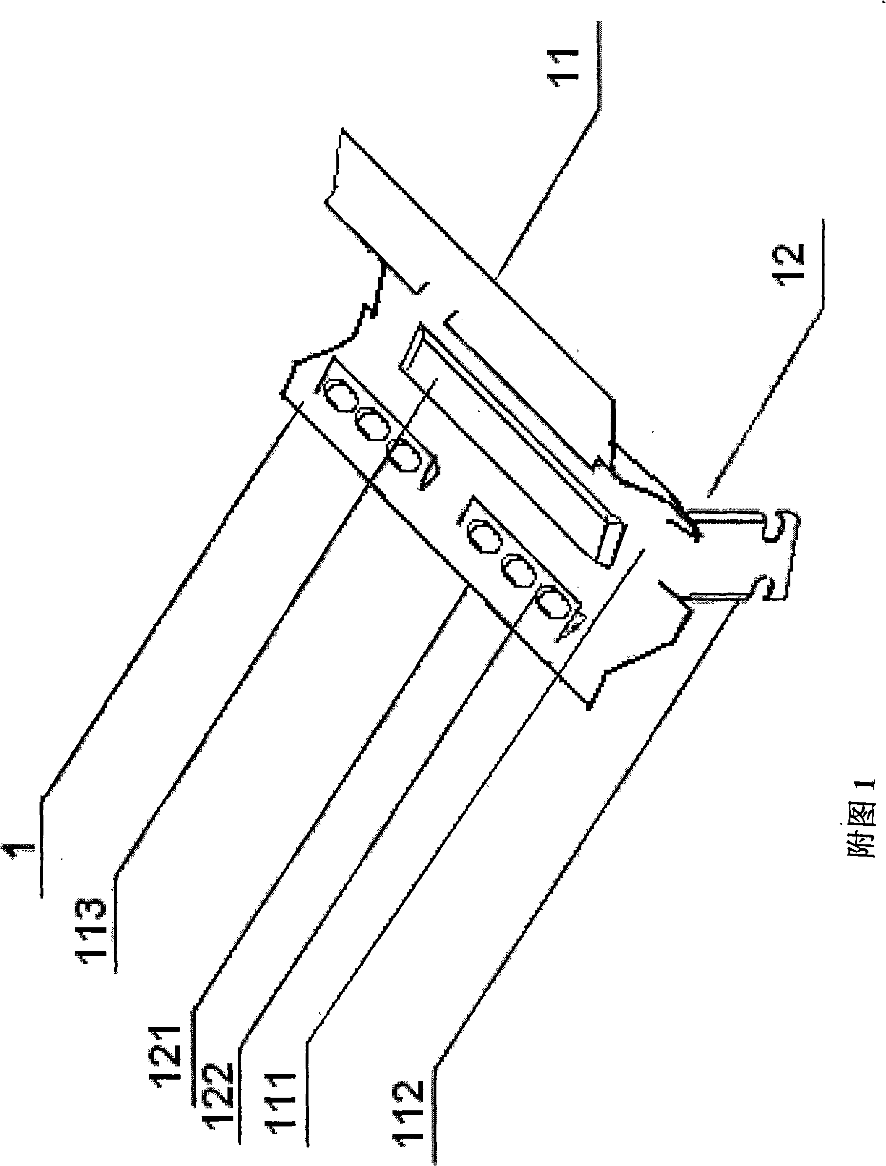
[0044] As shown in Figure 1, the float valve 1 is a strip-shaped valve body structure consisting of a valve body 11 and a filling member 12. The valve body 11 is composed of a valve plate 111 and a valve leg 112, and the filling member 12 is placed in the valve body. 11, and connected to the valve body 11.

[0045] There is a folded edge 121 on the stuffing member 12, and the folded edge 121 has two symmetrical structures, and a side edge 122 is formed on the folded edge 121 inwardly, and a side seam is formed under the side edge 122.

[0046] A raised structure 113 is punched on the top of the valve plate 111 in the length direction, and there are side seams on both sides of the raised structure.

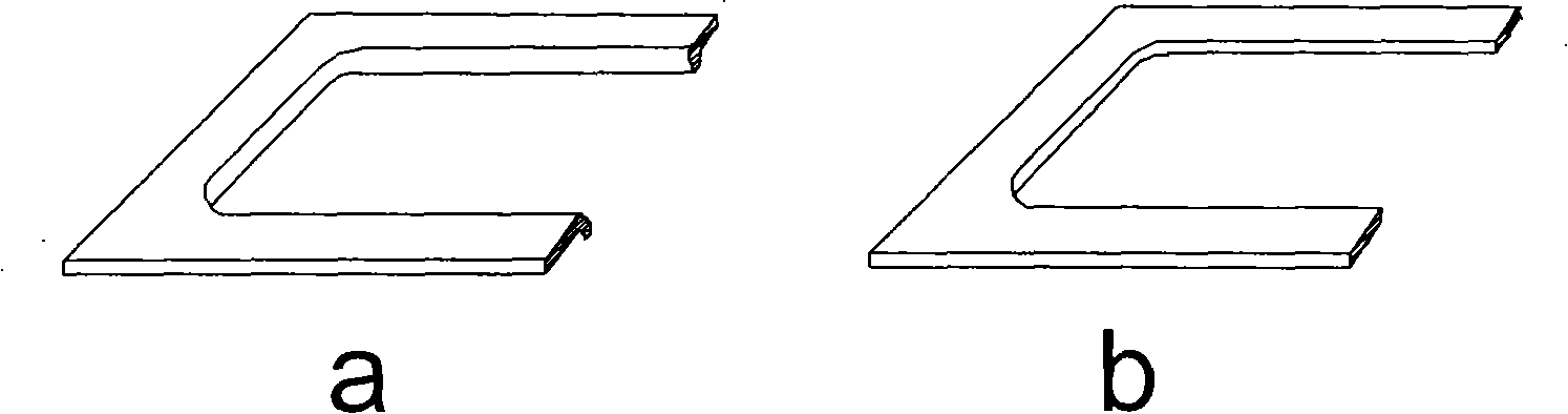
[0047] The valve plate 111 is either strip-shaped, oval, diamond-shaped, trapezoidal, or any combination of the above shapes; the shapes of both ends of the valve plate 111 are either th...


PUM


Abstract

The invention relates to a stuffing floating valve tray which consists of a floating valve (1) and a tray (2). The floating valve (1) is installed in a valve opening (21) and is hung at the tray (2). The stuffing floating valve tray is characterized in that the floating valve (1) has a rectangle structure formed by a valve body (11) and a stuffing part (12); the valve body (11) consists of a valve plate (111) and a valve leg (112); the stuffing part (12) is positioned at the upper part of the valve body (11), and is connected with the valve body (11). Compared with the prior art, the stuffing floating valve tray integrates the characteristics of the floating valve tray and that of the stuffing, thus not only having the advantages of large stuffing interface contact area, comparatively low voltage drop and comparatively high tray efficiency, but also being characterized in that the floating valve tray has large operation flexibility and high processing ability. The stuffing floating tray is applicable to regular type gas-liquid tower devices and ultra-large type gas-liquid tray devices with normal pressure system and pressurized system.

Description

technical field [0001] The invention is a packing valve tray used in separation towers in the field of petroleum and chemical industry. Background technique [0002] Tower equipment can be divided into two types: tray tower and packed tower. Due to the difference in structure, the mechanism of dispersion-interphase mass transfer-phase separation between gas and liquid phases is different between plate tower and packed tower. The tray column is a step-by-step contact vapor-liquid mass transfer equipment. The gas passes through the tray in the form of bubbling or jetting, and is broken into bubbles to contact the liquid. It is a process of gas-liquid dispersion and mass transfer by losing the pressure drop of the tray. The gas-liquid phase separation after mass transfer requires a certain space; while the packed tower is a continuous contact gas-liquid mass transfer equipment, which is a mass transfer process between the gas-liquid phases achieved by dispersing the liquid thr...

Claims


Application Information

Patent Timeline
Patent Type & Authority Applications(China)
IPC IPC(8): B01D3/18
Inventor 刘艳升曹睿刘拥军
Owner CHINA UNIV OF PETROLEUM (BEIJING)
Why Eureka
Try Eureka