
Large-sized turbine generator stator core vibrating numerical computation method

A technology of steam turbine generator and stator core, applied in vibration testing, testing of machine/structural components, measuring devices, etc. Issues such as setting a range

Active Publication Date: 2008-10-08
SHANGHAI ELECTRIC POWER GENERATION EQUIPMENT CO LTD
View PDF0 Cites 9 Cited by
  • Summary
  • Abstract
  • Description
  • Claims
  • Application Information

AI Technical Summary

Problems solved by technology

Using this method to calculate the vibration of the stator core does not fully consider the steady-state forced vibration of the stator core under the action of alternating electromagnetic force. In terms of the model, the stator core is assumed to be a cylinder. Compared with the actual model, the model is too simplified; In terms of load, only the effect of the maximum electromagnetic force is considered, but the cosine function relationship of the electromagnetic force is not considered; when solving, the excitation frequency can only be set to a specific value, but not a range; in the result, only a certain Radial vibration amplitude at a frequency (such as double frequency), but the radial, tangential and algebraic displacement responses of the entire iron core at a specified frequency cannot be obtained, nor can the frequency response vibration within a certain frequency range be obtained. The amplitude curve is not conducive to a comprehensive and intuitive analysis of the core vibration

Method used


Image

  • Large-sized turbine generator stator core vibrating numerical computation method
  • Large-sized turbine generator stator core vibrating numerical computation method
  • Large-sized turbine generator stator core vibrating numerical computation method

Examples


Embodiment

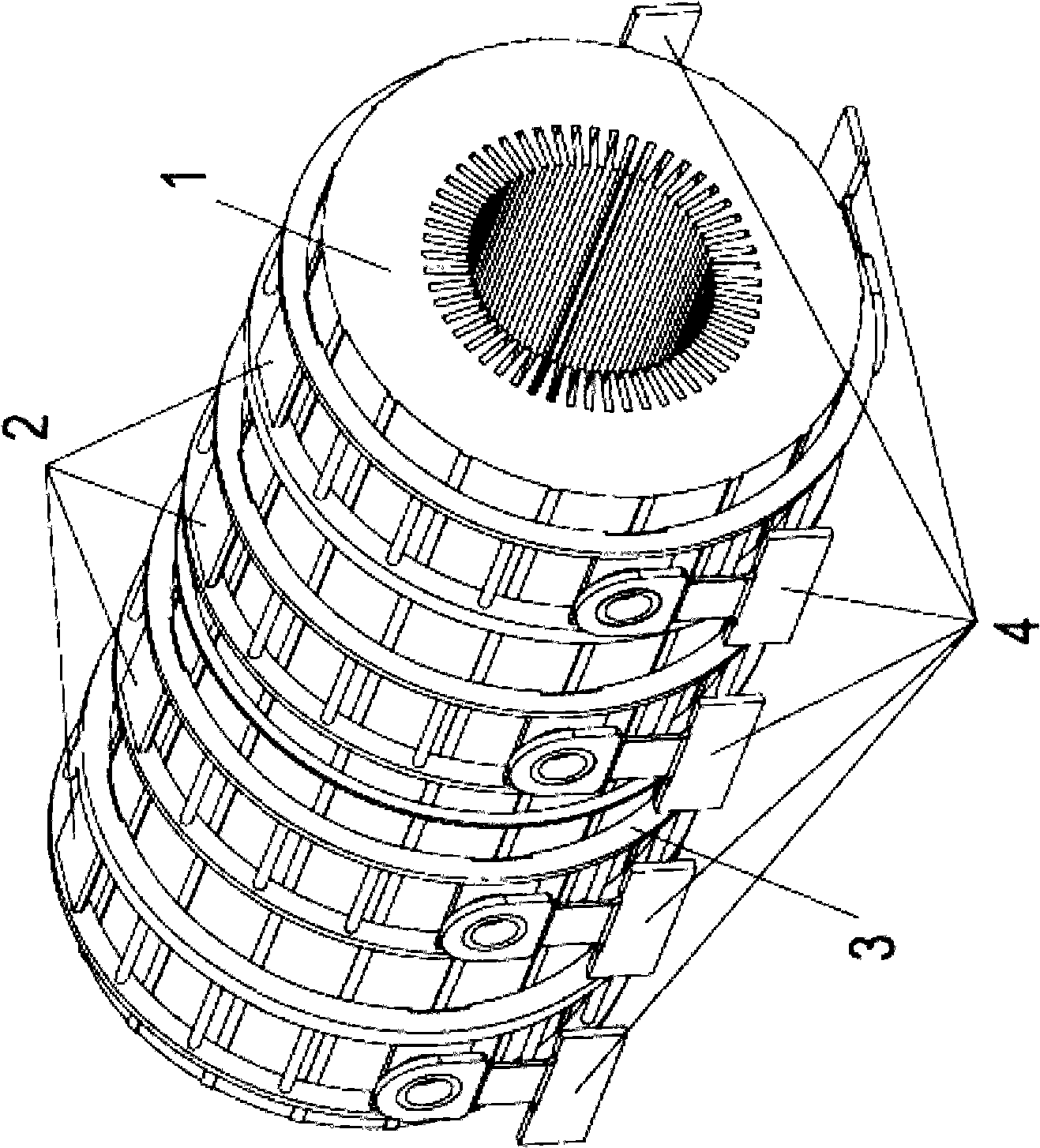
[0050] Such as figure 1 As shown, it is a simplified CAD model diagram of a large turbogenerator stator core, using the stator core of a certain large turbogenerator as the analysis object of the embodiment of the present invention, and its specific calculation steps are:

[0051] The first step, model simplification

[0052] According to the stator core drawing of a large steam turbine generator, the simplified stator core model is established by using Pro / E software. Neglecting the stiffness of the stator coil, the air duct and other gaps of the stator core are only considered for simple mass reduction, and the rest of the parts (including the stator core 150480kg, the stator coil 12260kg, the excitation end pressure ring 2508kg, the steam end All the weights of pressure ring 2508kg, iron core pressing 2470kg and magnetic shielding 2×680kg) are equivalent to iron core 1 with teeth, and four clamping rings 2 and one support ring 3 are welded to the iron core, ten springs Th...


PUM


Abstract

The invention relates to an algorithmic method used for analyzing vibration of a large-scale turbonator stator iron-core through numerical simulation on a computer and can be used for the vibration performance study of a turbonator stator iron-core. The invention is characterized by the simplified model of the large-scale turbonator stator iron-core, the calculation and conversion for magnetic pull force of the turbonator stator iron-core, the loading method of function and the result processing after harmonic response analysis, besides, displacement response of the stator iron-core in radial direction, tangential direction or other direction in frequency multiplication area or other frequency area can be directly obtained, the frequency response curve of the radial direction displacement, tangential direction displacement or algebra displacement can also be obtained. Compared with the prior algorithmic method, the invention has a more rapid and accurate result due to using function to load, the sustained momentum property of the large-scale turbonator stator iron-core can be forecasted by calculating the steady state vibration of the stator iron-core through the harmonic response analysis technology, testing and verifying whether the design can successfully overcome harmful effects caused by resonance, fatigue and other forced vibrations.

Description

technical field [0001] The invention relates to a vibration numerical calculation method of a stator iron core of a large steam turbine generator, which can be used for the vibration performance research of the stator iron core of a steam turbine generator and belongs to the technical field of the stator iron core of a generator. Background technique [0002] During the operation of a large generator, a rotating magnetic field passes through the stator core, which will generate alternating electromotive force, which will cause the core to loosen and generate noise, affecting the normal operation of the generator. What is more serious is that due to the magnetic pulling force generated by the rotation change of the rotor magnetic pole, the double frequency forced vibration is formed on the generator. If the natural frequency of the stator core is close to the double frequency, the vibration of the core will be amplified quickly, and the core will be Resonance may occur, resul...

Claims


Application Information

Patent Timeline
IPC IPC(8): G01M7/02
Inventor 李治黄磊张燕干保良徐钢峰
Owner SHANGHAI ELECTRIC POWER GENERATION EQUIPMENT CO LTD
Learn More