
Electrical heating biosafety steam sterilizer

A biosafety and steam sterilization technology, which is applied in the direction of heating, sanitary equipment for toilets, water supply equipment, etc., can solve the problem of not being able to effectively separate the sterile area from the sterile area, the boiler steam pressure is unstable, and the aseptic condition cannot be solved. To achieve the effect of compact structure, convenient control and improved sterilization efficiency

Inactive Publication Date: 2008-10-15
SHINVA MEDICAL INSTR CO LTD
View PDF0 Cites 5 Cited by
  • Summary
  • Abstract
  • Description
  • Claims
  • Application Information

AI Technical Summary

Problems solved by technology

The main defects that exist are: (1) The waste gas and waste liquid drawn out by vacuuming during use are all directly discharged. Since the waste gas and waste water have been in full contact with the sterilized objects, they will contain a large number of bacteria and viruses and are directly discharged. It will cause pollution to the environment, especially some waste gas and waste liquid containing highly infectious bacteria and viruses. Direct discharge will cause serious harm to society and people; (2) The steam source of the steam used is a boiler, which not only requires a large The land is large, and a separate boiler room is required. Since the sterilizer and the boiler are installed separately, the pipeline is long and the heat loss is large, and the boiler is generally a coal-fired boiler, which not only emits waste residue and exhaust gas, but also seriously pollutes the environment. One boiler supplies steam to multiple equipment, and the steam consumption is not synchronized, which causes the steam pressure of the boiler to be unstable, and also affects the sterilization quality; (3) For a closed space, it cannot effectively separate the sterile area from the sterile area , sterility cannot be guaranteed

Method used


Image

  • Electrical heating biosafety steam sterilizer
  • Electrical heating biosafety steam sterilizer

Examples


Embodiment Construction

[0023] The present invention will be further described in conjunction with the accompanying drawings of the above-mentioned embodiments.

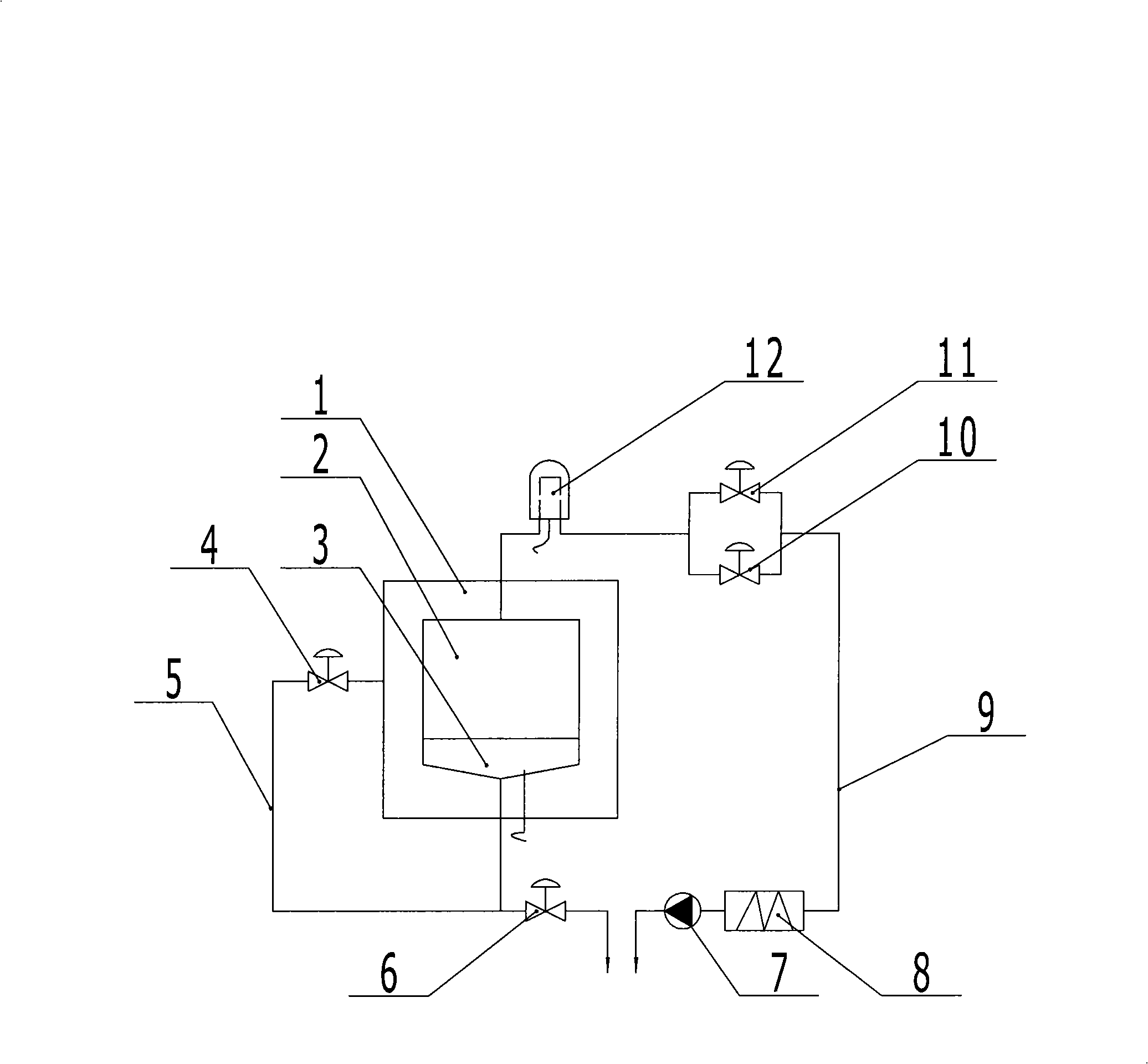
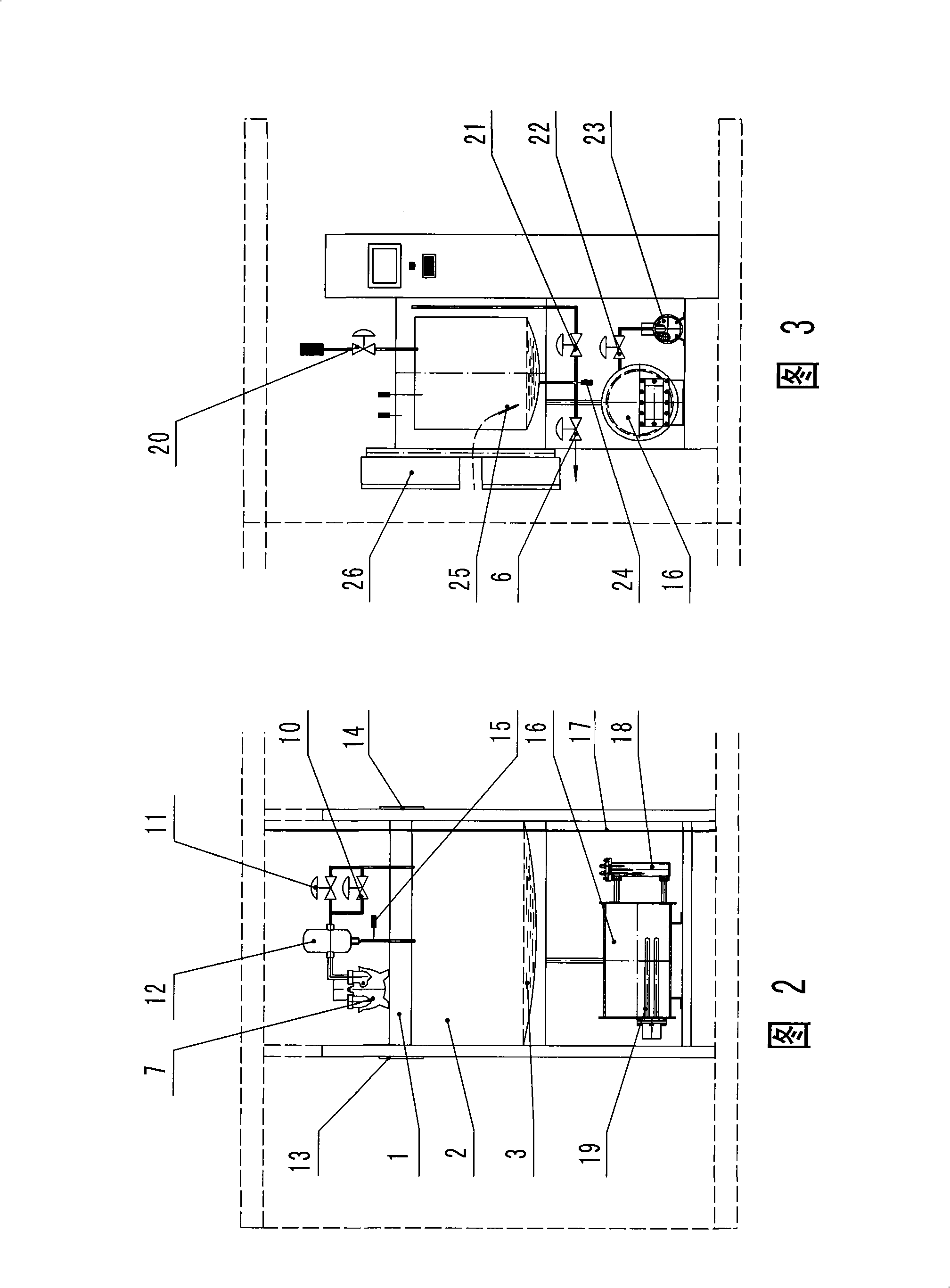
[0024] like figure 1 , shown in Fig. 2 and Fig. 3, electric heating biosafety steam sterilizer of the present invention comprises sterilizer main body, sterilization chamber 2, steam pipeline 5 and vacuumizing pipeline 9, sterilization chamber 2 cavities The wall is a sandwich structure, the interlayer 1 is connected to the steam pipeline 5, the steam pipeline 5 and the vacuum pipeline 9 are respectively connected to the sterilization chamber 2, and the bottom of the sterilization chamber 2 is in the shape of a sunken sump, which can be curved. The electric heating steam generator is communicated with the bottom of the sterilization chamber 2. The electric heating steam generator is an airtight container 16, and an electric heating tube 19 is installed in the airtight container 16. The airtight container 16 is also connected with a water pu...


PUM


Abstract

The invention relates to an electrical heating biosafety steam sterilizer, which is a sterilizing device for medical use. The sterilizer comprises a sterilizer main body, a sterilizing chamber, a steam pipeline, an evacuation pipeline, and touch screen control devices. The steam pipeline and the evacuation pipe respectively communicate with the sterilizing chamber having a concave water collecting trough-shaped bottom. The high pressure steam pipeline communicates with an electrical heating steam generator and the sterilizing chamber bottom. The waste generated during sterilizing can be inactivated secondarily to maintain sterile discharge and protect environment. The electrical heating steam generator is directly employed for providing steam, with compact structure, low investment, no coal fired pollution, stable performance, convenient control, and ensured sterilizing quality. Furthermore, a sealing plate is employed for effective sealing and isolating to maintain sterile condition, with good safety and reliability. Two sets of touch screen control devices maximally satisfy the man machine interaction, and are convenient for observation and control.

Description

technical field [0001] The invention relates to an electric heating biosafety steam sterilizer, which is medical sterilization equipment. Background technique [0002] Electric heating biosafety steam sterilizer, close to the pulsating vacuum sterilizer, including the main body of the sterilizer, sterilization chamber, steam pipeline, vacuum pipeline and touch screen control device, the steam pipeline and vacuum pipeline are respectively connected to sterilize room. When in use, put the object to be sterilized into the sterilization chamber, evacuate the sterilization chamber, and directly discharge the extracted waste gas and waste liquid, and then inject steam into the sterilization chamber to sterilize the items and sterilize them. After the end, vacuum dry the items, and then return to the end. The main defects that exist are: (1) The waste gas and waste liquid drawn out by vacuuming during use are all directly discharged. Since the waste gas and waste water have been ...

Claims


Application Information

Patent Timeline
IPC IPC(8): A61L2/07A61L2/04A61L2/24
Inventor 屈靖韩健康姜艳锋王飞崔洪章王鹏飞
Owner SHINVA MEDICAL INSTR CO LTD
Learn More