Steam turbine rotor blades cover band structure and its machining process

A technology of moving blades and steam turbines, which is applied in the direction of supporting components of blades, machines/engines, mechanical equipment, etc., and can solve problems such as increasing unit noise, reducing steam work efficiency, and consuming energy

Active Publication Date: 2008-10-15
DONGFANG TURBINE CO LTD
View PDF0 Cites 17 Cited by
  • Summary
  • Abstract
  • Description
  • Claims
  • Application Information

AI Technical Summary

Problems solved by technology

But it also brings new problems: Since the matching structure of the blade shroud is designed according to the static state, when the unit is in static state, the two axial end faces of the shroud (ie, the end faces of the steam inlet side and the steam outlet side) are flush, When the unit is running, the blades are twisted under the action of centrifugal force, the axial end faces of the ad

Method used


Image

  • Steam turbine rotor blades cover band structure and its machining process
  • Steam turbine rotor blades cover band structure and its machining process
  • Steam turbine rotor blades cover band structure and its machining process

Examples


Embodiment Construction

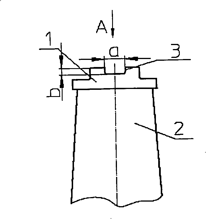
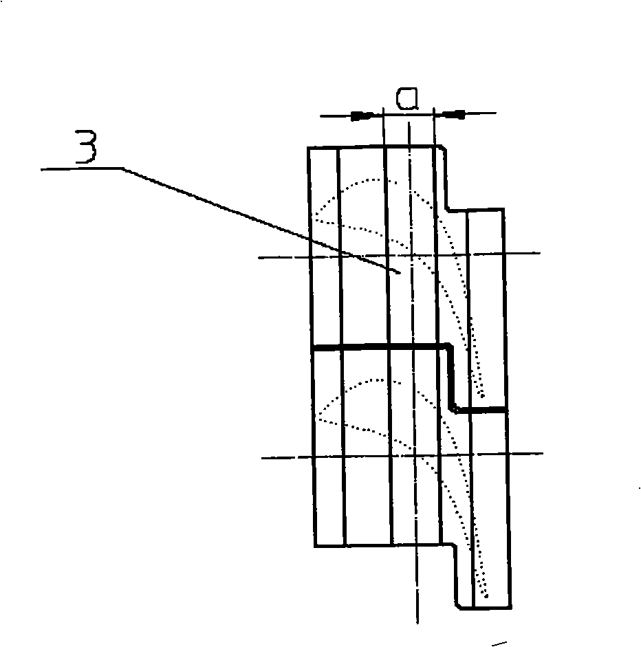
[0031] see figure 1 , figure 2 : The shroud 1 is located on the top of the blade body 2. When processing the blades, a machining allowance is reserved on the end faces of the inlet and outlet steam sides and the top surface of the shroud 1, and then all the blades are packed into the impeller so that the shrouds of all blades 1 is combined to form a ring to form a shroud, and an annular process groove 3 is turned on the outer peripheral surface of the shroud (ie, the top surface of the blade shroud), the groove has a width of a and a depth of b.

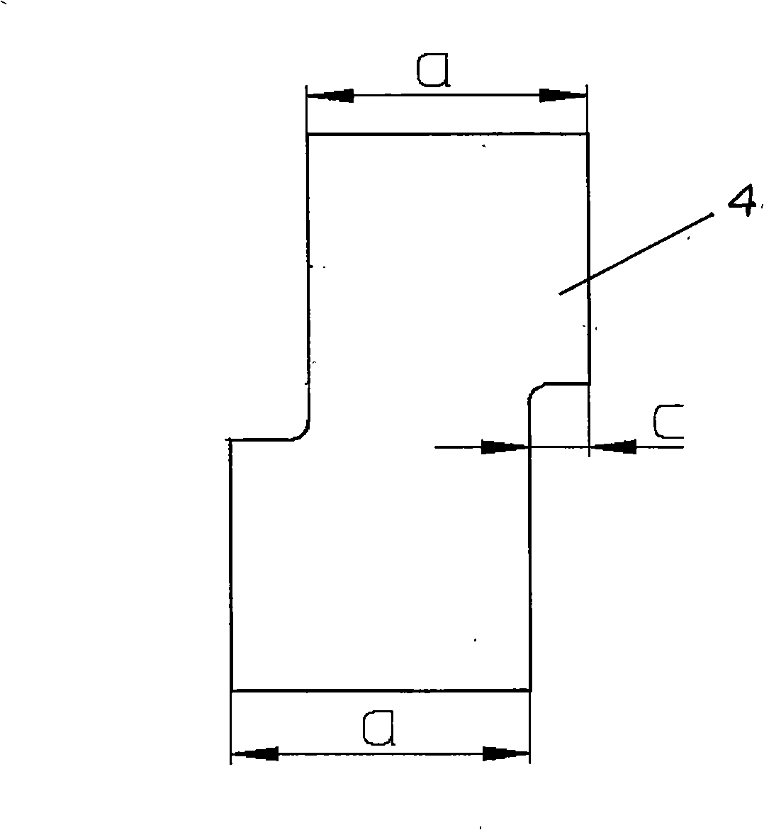
[0032] see image 3 , Figure 4 : Process a batch of process blocks 4, the geometric dimensions of the process block 4 are compatible with the process tank 3, the process block 4 has two block parts of the overall structure, and the two block parts are parallel and dislocated, and the dislocation distance C is equal to the blade torsion The dislocation distance between the two adjacent leaf crowns.

[0033] See Fig. 5: apply ext...


PUM


Abstract

The invention discloses a shroud structure of a turbine rotor blade and the processing technology of the same. A plurality of rotor blades with blade tips are arranged on a blade wheel of a turbine rotor, the blade tips of adjacent rotor blades are in fit with each other to combine a ring and form the shroud; when the turbine is static and the rotor blade is not twisted, two axial end surfaces of the shroud are indented, when the turbine runs and the rotor blade is twisted, two axial end surfaces of the shroud are on the same level. The processing technology comprises the steps of: (1) processing a plurality of pre-twisted process modules each of which comprises two module-shaped parts of the whole structure, the two module-shaped parts are alternative in parallel with the alternative distance equal to the alternative distance between two adjacent blade tips after the blades are twisted; (2) arranging all blades on the blade wheel, lathing a circular groove which matches with the pre-twisted process modules in width on a peripheral surface of the shroud; (3) twisting and putting the blades in the pre-twisted process modules; (4) lathing two axial end surfaces of the shroud to be on the same level; (5) dismounting the pre-twisted blocks (6) lathing the peripheral surface of the shroud.

Description

technical field [0001] The invention relates to a steam turbine moving blade, in particular to the shroud structure of the moving blade and its processing technology. technical background [0002] The shroud is one of the main components of the steam turbine rotor. It is ring-shaped, and its inner peripheral surface is connected to the top of the moving blades to surround all the moving blades. The shroud and the moving blades are combined to form a steam passage. Every two adjacent blades The space between is a steam channel. The traditional shroud is an independent part. When assembled, it is riveted / welded on the top of the blade. This rigid connection makes the dynamic stress of the rotor large and the safety is not high, and because the blade cannot be twisted, the aerodynamic characteristics of the unit are poor. . After the advent of the self-contained crown blade, the shroud is no longer an independent part, but is composed of the crowns of all blades. The crown of...

Claims


Application Information

Patent Timeline
IPC IPC(8): F01D5/22
Inventor 周振杰吴其林周显丁范小平李伯武曹守洪赵萍钟钢云胡国光李银凤贺伟
Owner DONGFANG TURBINE CO LTD
Why Eureka
Try Eureka