Burnable granule material combustion plant
A technology for burning equipment and granular materials, which is applied in the direction of gas fuel burners, burners, and combustion methods. Effects of promoting waste utilization, simple structure, and preventing environmental pollution
Inactive Publication Date: 2008-10-15
张荣耀
View PDF1 Cites 4 Cited by
- Summary
- Abstract
- Description
- Claims
- Application Information
AI Technical Summary
Problems solved by technology
Currently known and improved stoves are difficult to burn combustible particulate materials efficiently and in large quantities, especially those with high density. The applicant’s other Chinese patent application 200710030568 (Volume 24, published on the No. 09 Invention Patent Bulletin) Combustion of particulate materials, and pollute the environment
Although some burners can burn a large amount of combustible particulate materials and improve environmental benefits, they still have complex structures and are difficult to be used with stoves and boilers for cooking, heating, steam, etc., and there are still a lot of dust and smoke discharged to pollute the environment. It is still difficult to burn the above-mentioned dense particulate materials for combustion
Method used
View moreImage
Smart ImageViewing Examples

Examples
Embodiment Construction
Login to View More PUM
 Abstract
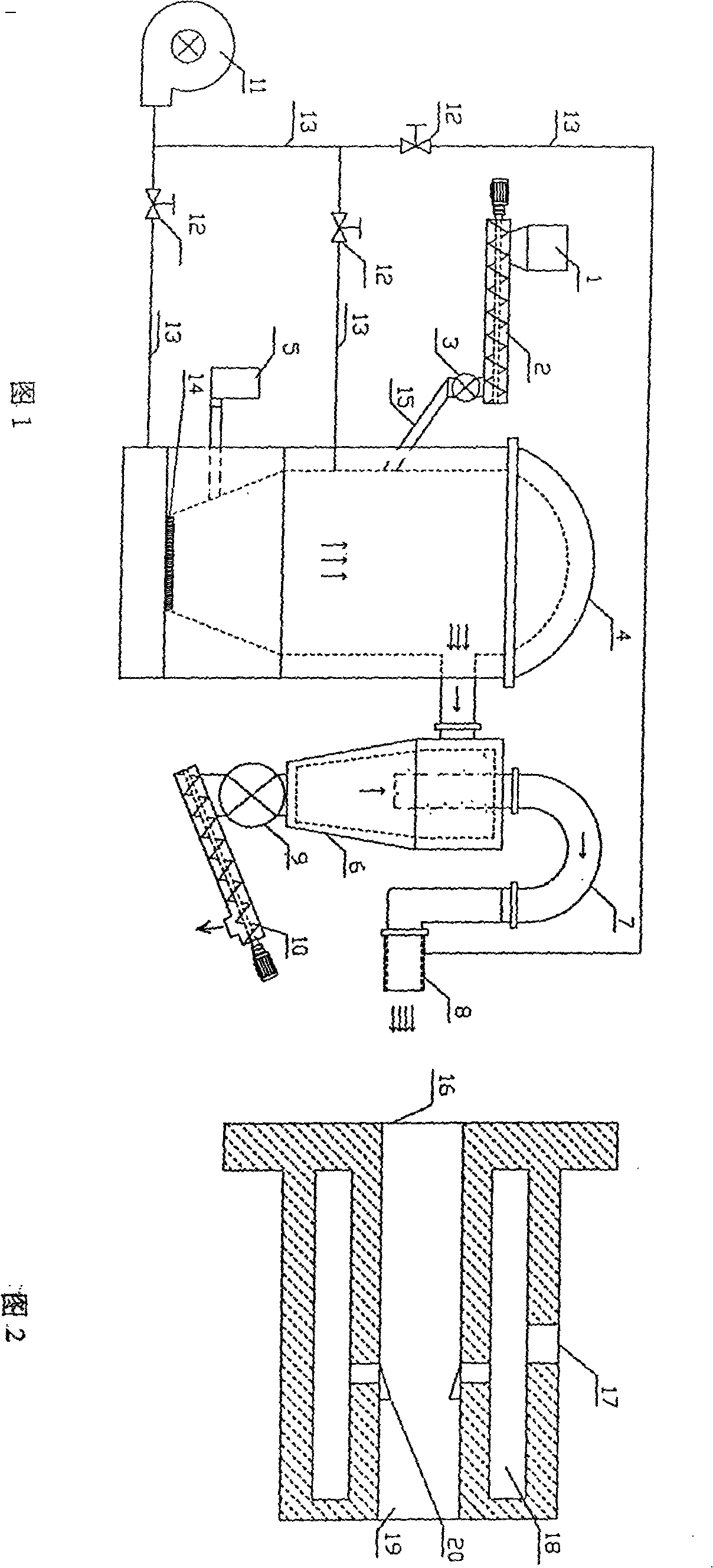
The invention discloses a combustion device for flammable grain material, comprising a bunker, a helicoid, an airlock, a furnace body, an igniter, an ash expeller, a furnace end, a blower, an air door and a conduit. The flammable grain materials enter into an internal cavity of the furnace body through material feeding to be combusted so as to produce flammable gases. The flammable gases enter into the furnace end to be primarily combusted so as to jet flames. The device has the advantages that the device, which is capable of effectively combusting the flammable grain materials in large scale and promoting waste utilization, regenerates energy and fertilizer, removes dusts and prevents environment from being polluted, and is easy to be cooperated with stoves and boilers, is large in social and economic benefits. The device is widely applicable for domestic use and industries, in particular being suitable for combusting high density flame-retardant flammable grain materials.
Description
Combustible particulate material combustion equipment technical field The invention relates to a combustible particle material combustion equipment. Background technique Currently known and improved stoves are difficult to burn combustible particulate materials efficiently and in large quantities, especially those with high density. The applicant’s other Chinese patent application 200710030568 (Volume 24, published on the No. 09 Invention Patent Bulletin) Combustion of particulate materials, and pollute the environment. Although some burners can burn a large amount of combustible particulate materials and improve environmental benefits, they still have complex structures and are difficult to be used with stoves and boilers for cooking, heating, steam, etc., and there are still a lot of dust and smoke discharged to pollute the environment. It is still difficult to burn the above-mentioned dense particulate material for combustion. Contents of the invention The purpose ...
Claims
Login to View More Application Information
Patent Timeline
 Patent Type & Authority Applications(China)
IPC IPC(8): F24B1/18C10B53/02C10J3/20F24B13/04F23D14/60
Inventor 张荣耀
Owner 张荣耀
Features
- R&D
- Intellectual Property
- Life Sciences
- Materials
- Tech Scout
- Unparalleled Data Quality
- Higher Quality Content
- 60% Fewer Hallucinations
Learn More Browse by: Latest US Patents, China's latest patents, Technical Efficacy Thesaurus, Application Domain, Technology Topic, Popular Technical Reports.
© 2025 PatSnap. All rights reserved.Legal|Privacy policy|Modern Slavery Act Transparency Statement|Sitemap|About US| Contact US: help@patsnap.com