Photovoltaic cells comprising two photovoltaic cells and two photon sources

A photon source and photovoltaic cell technology, applied in the field of photovoltaic cells, can solve the problems of reduced efficiency, reduced device efficiency, and the inability of a single cell to be matched by current, so as to achieve the effect of high-efficiency power generation

Inactive Publication Date: 2008-10-22
IMPERIAL INNOVATIONS LTD
View PDF3 Cites 10 Cited by
  • Summary
  • Abstract
  • Description
  • Claims
  • Application Information

AI Technical Summary

Problems solved by technology

This means that, for most of the time, these individual cells cannot be current matched and the device efficiency drops from the recorded optimum under the conditions of the designed il

Method used


Image

  • Photovoltaic cells comprising two photovoltaic cells and two photon sources
  • Photovoltaic cells comprising two photovoltaic cells and two photon sources
  • Photovoltaic cells comprising two photovoltaic cells and two photon sources

Examples


Embodiment Construction

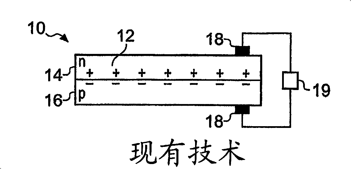
[0029] Figure 1 shows a schematic representation of a simple photovoltaic cell, such as a solar cell, according to the prior art. Cell 10 comprises a part 12 of semiconductor material, such as silicon, comprising a p-n junction, i.e., part 12 of semiconductor material comprises a first portion 14 (which is an n-type semiconductor) adjacent to a second portion 16 (which is a p-type semiconductor )set up. This arrangement creates an electric field across the p-n junction, generated by an ionized donor on one side and an ionized acceptor on the other. Electrical contacts 18 are provided on both sides of the battery 10 and thus of the p-n junction.

[0030] When a photon of electromagnetic radiation of suitable energy (e.g., in a suitable wavelength range) is incident on the cell 10 and is absorbed by the semiconductor, its energy transfers electrons from the semiconductor's valence band to the conduction band ( conduction band), thus generating electron-hole pairs. The electri...


PUM


Abstract

A photovoltaic device comprises an upper cell and a lower cell separated by an electrically insulating layer. The cells and the layers are fabricated as a single monolithic structure, and separate electrical contacts are provided for the upper and lower cells to allow independent extraction of current from each cell. The upper cell has a larger bandgap than the lower cell so that incident low energy photons unabsorbed and unconverted by the upper cell can propagate through to the lower cell for conversion. The two bandgaps can be selected to accommodate spectral' ranges of interest. The device is incorporated into a system including two sources of photons with different wavelength ranges associated with the bandgaps of the two cells, such that each cell can convert photons from one source. One source may be the sun and the other may be a local photon source such as a thermal source. Alternatively, both photon sources may be local sources. Operation of the device can be further optimised and extended by configuring the upper cell as a tandem cell or in a MIMS arrangement, or both.

Description

technical field [0001] This invention relates to photovoltaic cells. Background technique [0002] Power generation from photovoltaic cells has been a fact for many years, however, this does not constitute a significant part of the overall power generation. One reason for this is that photovoltaic power generation is more expensive than conventional power generation, mainly because the cost of a single photovoltaic cell is relatively high. There are two methods that can be used to reduce costs. One option is to make these cells from cheaper materials, but this usually results in lower conversion efficiencies. Alternatively, battery efficiency can be improved. High-efficiency cells can be used in solar concentrators (where light from the sun is collected over a large area and concentrated onto a small area of ​​photovoltaic cells), or in thermo-photovoltaic systems (where light is generated from sources such as fuel burning These cells are irradiated with high-intensity l...

Claims


Application Information

Patent Timeline
IPC IPC(8): H01L31/072H01L31/068H01L31/075H01L31/078H01L31/055H01L31/058H01L25/04H01L27/146
CPCH01L2924/0002H01L31/061H01L27/14647H01L27/1422Y02E10/50H01L31/0406H01L31/078H01L25/045H01L31/043H01L31/0475H02S10/30Y02E10/52H01L2924/00H01L31/04
Inventor 基思·威廉·约翰·巴恩哈姆马西莫·马泽尔伊恩·马克·巴拉德
Owner IMPERIAL INNOVATIONS LTD
Why Eureka
Try Eureka