Fluorescent powder thin film for light emitting diode

A technology of light-emitting diodes and phosphors, applied in electrical components, electrical solid devices, circuits, etc., can solve problems such as difficulty in controlling the consistency of quality, uneven thickness of phosphors, and inability to produce excellent light, saving time and money , a wide range of applications, the effect of easy operation

Inactive Publication Date: 2008-10-29
林善仁
View PDF0 Cites 12 Cited by
  • Summary
  • Abstract
  • Description
  • Claims
  • Application Information

AI Technical Summary

Problems solved by technology

Furthermore, after the phosphor powder is dispensed and covers the chip, the phosphor powder will precipitate during baking and curing, so that the thickness of the phosphor powder will be uneven around the chip, so that the white light emitting diodes produced in the same batch will not be uniform

Method used


Image

  • Fluorescent powder thin film for light emitting diode
  • Fluorescent powder thin film for light emitting diode
  • Fluorescent powder thin film for light emitting diode

Examples


Embodiment Construction

[0025] In order to further reveal the specific technical content of the present invention, please refer to the accompanying drawings.

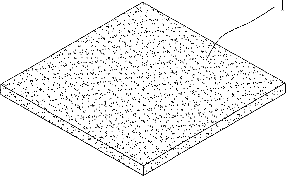
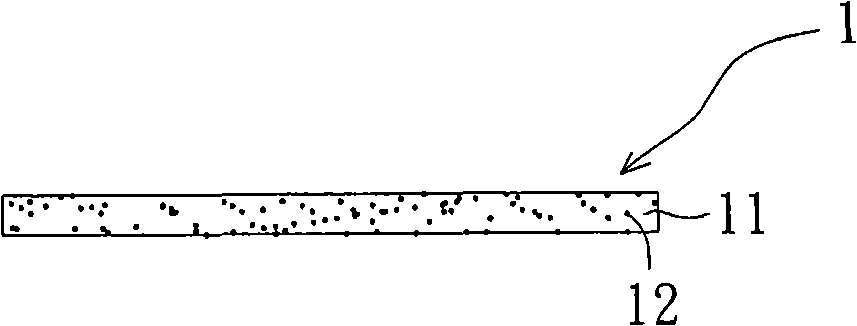
[0026] like Figure 2 to Figure 3 As shown, basically, the present invention is used for the phosphor powder film 1 of light-emitting diodes, which utilizes an appropriate amount of any transparent glue or transparent plastic material 11 and phosphor powder 12 to mix and stir evenly according to an appropriate ratio, and then coat it on a flat surface. on the fixture, and put it into the ultrasonic vibration arrangement mechanism and let it stand for a period of time, so that the fluorescent powder 12 can be fully and uniformly deposited on the surface of the plane fixture, and then the required phosphor film 1 is made, and finally the phosphor The powder film 1 is sent into a baking oven for baking, and becomes the finished phosphor film 1 after curing. However, the above-mentioned film-forming method is only one of the embodiments, and it i...


PUM


Abstract

The invention relates to a phosphor thin film used for a light emitting diode, which is prepared by blending and mixing evenly any adequate transparent adhesive solution or transparent plastic material and phosphor powder together according to appropriate proportion, and then making the adhesive solution into a thin film shape.

Description

technical field [0001] The invention is a fluorescent powder film, especially a fluorescent powder film used for light-emitting diodes. Background technique [0002] In order to make traditional high-power light-emitting diodes have different color light emitting methods, such as emitting white light, the known manufacturing process is to dispense blue light-emitting chips (InGaN) through glue containing yellow phosphor (Yellow Phosphor), so that the glue Liquid covers the chip, and the principle of light mixing is that the blue light emitted by the chip excites the yellow phosphor in the glue to emit yellow light, so that the two colors of light are mixed to form white light. [0003] like figure 1 As shown, it is a schematic diagram of a traditional high-power light-emitting diode (LED) packaged phosphor, and its preparation process is as follows: [0004] (1) Die-fixing step: first apply silver glue on the lead frame 10, then paste the blue-ray chip 20 on the lead frame...

Claims


Application Information

Patent Timeline
IPC IPC(8): H01L33/00H01L33/50
CPCH01L2224/48247
Inventor 林善仁
Owner 林善仁
Why Eureka
Try Eureka