
Modified oscillator and decompression power converter

A technology for oscillators and power supplies, applied in the direction of output power conversion devices, conversion equipment without intermediate conversion to AC, instruments, etc., can solve problems such as low switching frequency, adjustment of speed error amplifier output current limit, etc., to improve transient Responsive, small size effects

Inactive Publication Date: 2008-10-29
WUXI ZGMICRO ELECTRONICS CO LTD
View PDF0 Cites 13 Cited by
  • Summary
  • Abstract
  • Description
  • Claims
  • Application Information

AI Technical Summary

Problems solved by technology

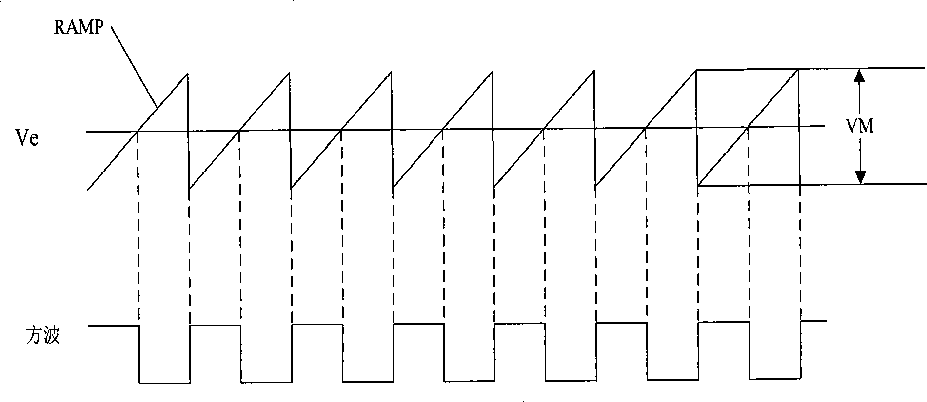
The speed of loop adjustment to Ve is limited by the loop bandwidth and the output current of the error amplifier, usually very slow, much lower than the switching frequency

Method used


Image

  • Modified oscillator and decompression power converter
  • Modified oscillator and decompression power converter
  • Modified oscillator and decompression power converter

Examples


Embodiment Construction

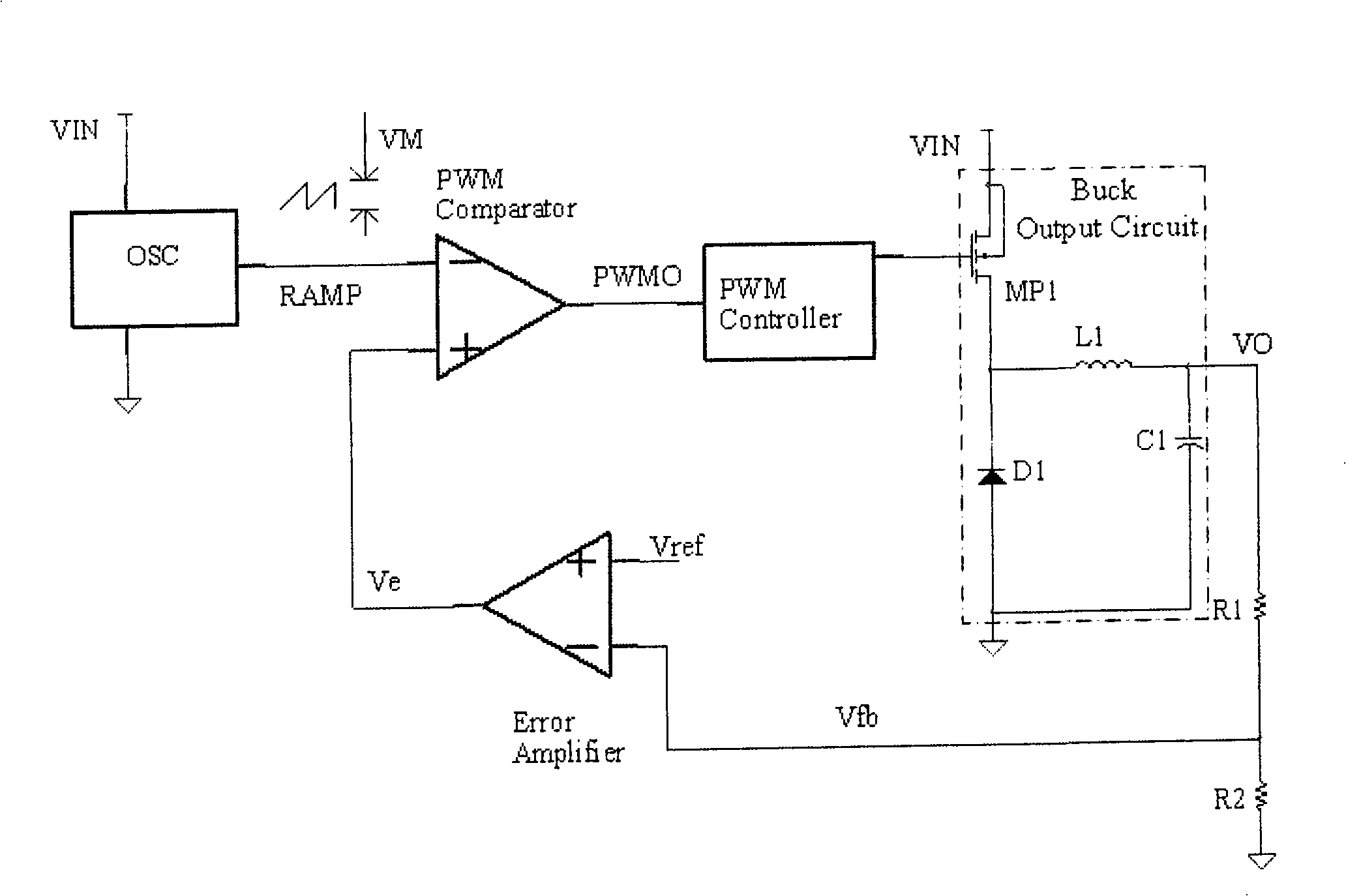
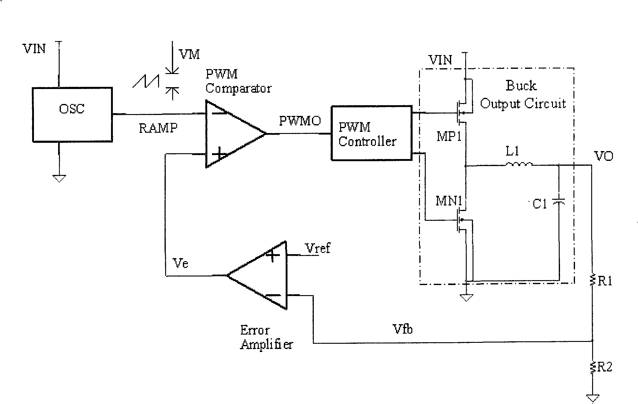
[0030] The invention is right Figure 1A with 1B improvement of. Therefore, it is necessary to understand Figure 1A with 1B The specific details and work process.

[0031] Figure 1A with 1B It is the circuit diagram of two kinds of step-down power converters. The difference between the two lies in the realization of the step-down output circuit. As described in the background art, the step-down power conversion circuit usually includes a buck output circuit (Buck Output Circuit), a voltage divider network composed of a resistor R1 and a resistor R2, an error amplifier (Error Amplifier), and an oscillator ( Oscillator, OSC for short), Pulse Width Modulation Comparator (PWMComparator for short), and PMW Controller. For clarity and conciseness, the functions of the above-mentioned modules will not be repeated here.

[0032] See Figure 1A As shown, the step-down output circuit includes a PMOS transistor MP1, a diode D1, an output inductor L1, and an output capacitor C1. The source ...


PUM


Abstract

The invention discloses an oscillator which comprises a voltage division circuit, a charging resistance, a capacitance, a comparator circuit and a discharging circuit. The voltage division circuit is connected with a power source and provides a divided voltage reflecting the voltage of the power source; the power source charges the capacitance by the charging resistance; the comparator circuit compares the voltage drop of the capacitance and the divided voltage; when the voltage drop of the capacitance is higher than or equal to the divided voltage, the comparator circuit outputs a discharge control signal to control the discharging circuit to discharge the capacitance; when the voltage drop of the capacitance is lower than the divided voltage, the comparator circuit outputs a non-discharge control signal to control the discharging circuit to stop discharging the capacitance; thus the oscillator generates a oscillator signal, the amplitude of which is in proportion to the power source voltage.

Description

Technical field [0001] The invention relates to a low-voltage oscillator, in particular to an improved oscillator and a step-down power converter using the oscillator. Background technique [0002] DC-DC circuits are widely used in power management circuits in mobile electronic devices, and a Buck Power converter is a very commonly used DC-DC circuit. [0003] Figure 1A , 1B The schematic diagrams of two step-down power conversion circuits are respectively. The step-down power conversion circuit usually includes a step-down output circuit (Buck Output Circuit), a voltage divider network composed of a resistor R1 and a resistor R2, an error amplifier (Error Amplifier), an oscillator (Oscillator, OSC), pulse width modulation Comparator (Pulse Width Modulation Comparator, referred to as PWM Comparator), pulse width modulation controller (PMWController). [0004] The step-down output circuit is used to receive the input voltage VIN and generate the output voltage VO according to th...

Claims


Application Information

Patent Timeline
Patent Type & Authority Applications(China)
IPC IPC(8): H02M3/10H02M3/155H02M3/156
Inventor 王钊尹航田文博
Owner WUXI ZGMICRO ELECTRONICS CO LTD
Learn More