
Method and instrument for calibrating rotary shaft coaxiality

A calibration method and rotary shaft technology, applied to instruments, measuring devices, optical devices, etc., can solve the problems that cannot meet the installation accuracy requirements of the reel shaft and the high coaxiality requirements of the rotary shaft, etc., and achieve a high degree of automation , improve work efficiency, and achieve high calibration accuracy

Inactive Publication Date: 2008-11-05
项龙骧
View PDF0 Cites 26 Cited by
  • Summary
  • Abstract
  • Description
  • Claims
  • Application Information

AI Technical Summary

Problems solved by technology

For example, for container cranes, the length of the lifting reel is up to 8 meters. The above-mentioned measurement and calibration method obviously cannot meet the accuracy requirements for the installation of the reel shaft; the fan unit in chemical equipment has a diameter of more than 1 meter. Requirements are also high; especially for ship shafting with large axial lengths

Method used


Image

  • Method and instrument for calibrating rotary shaft coaxiality
  • Method and instrument for calibrating rotary shaft coaxiality
  • Method and instrument for calibrating rotary shaft coaxiality

Examples


Embodiment Construction

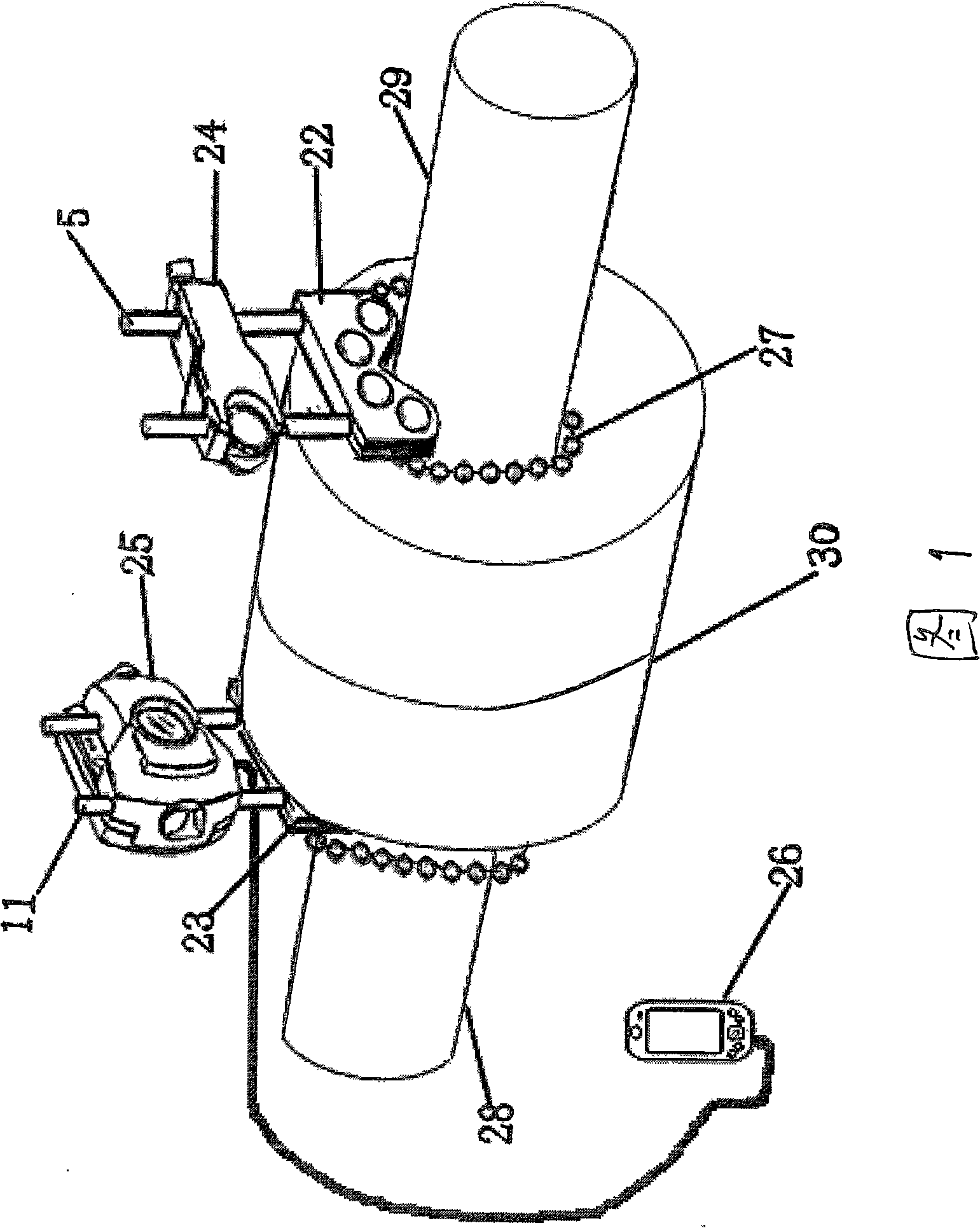
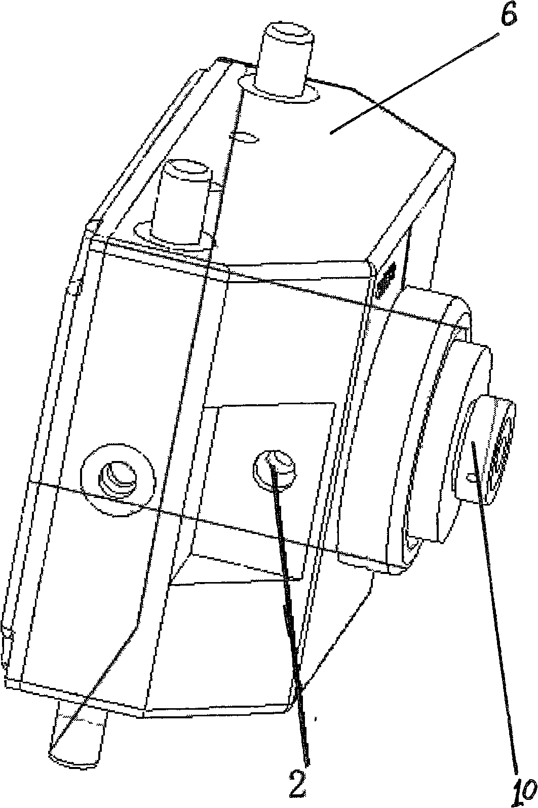
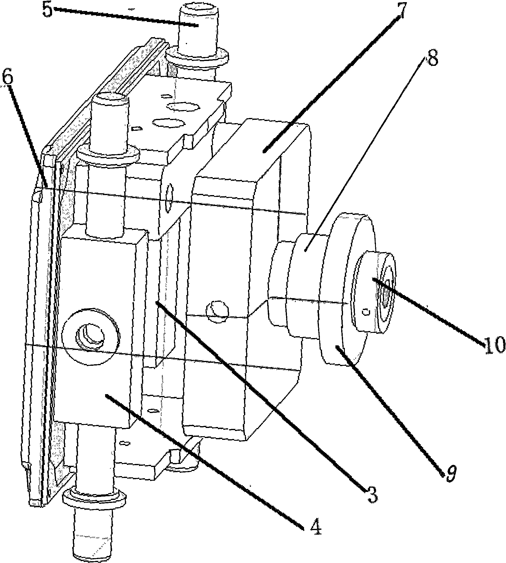
[0014] Refer to Figure 1 to Figure 5 , the method for calibrating the coaxiality of the rotary shaft in the present invention is as follows: firstly, the laser transmitter support and the laser receiver support are respectively fixed on the two rotary shafts to be measured, and then the laser transmitter and the laser receiver are respectively loaded into their respective on the support, and make their heights roughly equal, even if the laser emitted by the laser transmitter falls near the center of the filter (lens) of the laser receiver, and then use a chain to respectively connect the laser transmitter support and the laser receiver support Locked with the two rotating shafts to be tested; then, the laser beam is emitted by the laser collimator of the laser transmitter and directed to the optical filter (lens) in the laser receiver. After the action of the optical filter, only the wavelength 650nm laser (the diameter of the laser beam is less than or equal to 3mm), and the...


PUM


Abstract

An adjusting method of a rotor proper alignment is disclosed, wherein a laser emitter and the laser emitter seat and a laser receiver and a laser receiver seat are respectively fixed on the two rotors; then the laser emitter transmits the laser to the light filter of the laser receiver, then passes through the half reflection lens to form two vertical lasers and transmits to the photosurfaces of the two vertical two-dimensional position sensitive sensors. When in measurement, two axes to be measured rotate in the same direction, and the position coordinate signal of the facula when acquiring the different corners and is input into the portable laser receiver, which is electrically connected with the portable data analyzer. The invention has high automatization degree, high adjusting precision, which increases the working efficiency of the rotor proper alignment.

Description

1. Technical field [0001] The invention relates to a method for calibrating the coaxiality (commonly known as "centering") of a rotary shaft and a calibrator thereof. 2. Background technology [0002] At present, all kinds of mechanical equipment are used in machinery, chemical industry, petroleum, vehicle, electric power and other industries, and mechanical transmission systems are widely used in these mechanical equipment, which transfer the power and motion of prime movers (such as electric motors and internal combustion engines) It is transmitted to various actuators, so "prime mover-coupling-drive shaft" has become a commonly used transmission method. The connection of these shaft systems has high requirements on the coaxiality of the relevant rotary shafts (commonly known as centering), otherwise it will cause vibration and noise of the machine, shorten the service life of the machine, and even cause serious accidents. [0003] The existing calibration for the coaxial...

Claims


Application Information

Patent Timeline
IPC IPC(8): G01B11/27
Inventor 孙世基项龙骧张国庆
Owner 项龙骧
Features
  • Generate Ideas
  • Intellectual Property
  • Life Sciences
  • Materials
  • Tech Scout
  • Unparalleled Data Quality
  • Higher Quality Content
  • 60% Fewer Hallucinations
Learn More