
Invisible apparatus and design based on geometrical optics

A geometrical optics, invisible technology, applied in optics, optical components, beam optical fibers, etc., can solve the problems of special material requirements and complex structure, and achieve the effect of low cost, simple structure and easy production

Inactive Publication Date: 2008-11-05
上海市第二中学
View PDF0 Cites 27 Cited by
  • Summary
  • Abstract
  • Description
  • Claims
  • Application Information

AI Technical Summary

Problems solved by technology

There are deficiencies such as complex structure, special material requirements, and the use of external light sources

Method used


Image

  • Invisible apparatus and design based on geometrical optics
  • Invisible apparatus and design based on geometrical optics
  • Invisible apparatus and design based on geometrical optics

Examples


Embodiment 1

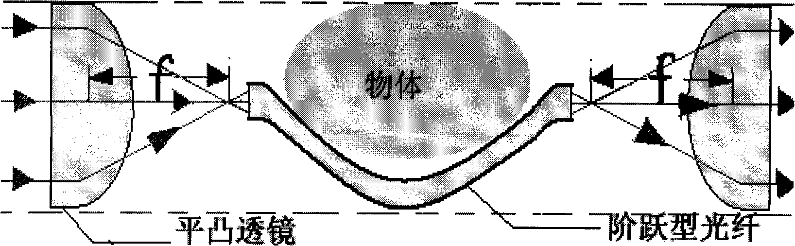
[0053] At least one group is composed of an object group 1 that allows light to pass through and focus it, and a light beam transmission component 2 and an invisible area 3 arranged between the focused object group 1 . Wherein, the object group 1 for focusing light is a plano-convex lens group, and the light beam transmission component is an optical fiber.

[0054] When a beam of parallel light is irradiated to the front of the object, it will be converged into a small beam and injected into one end of the image-transmitting fiber, and then transmitted through the image-transmitting fiber (step-type fiber bundle), (because the fiber is flexible, it can be bent into any Shape, so that it goes around from the front of the object to the back of the object) At the other end of the image transmission fiber, the converged light beam will be emitted and diverged into parallel light, and finally imaged to achieve the invisible effect (as attachedfigure 1 shown).

[0055] In this embod...

Embodiment 2

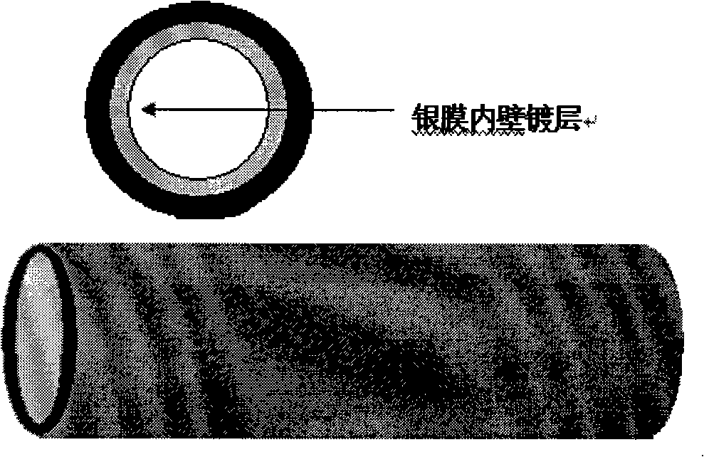
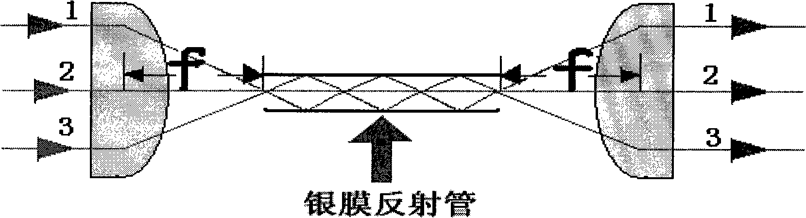
[0057] It is composed of an object group 1 that allows light to pass through and focus it, and a light beam transmission component 2 and an invisible area 3 arranged between the focused object group 1 . Wherein, the object group 1 for light focusing adopts a plano-convex lens group, and the light beam transmission part 2 is a silver film reflection tube. Among them, the structure of the silver film reflection tube is as attached Figure 2a shown; working principle as attached Figure 2b shown.

Embodiment 3

[0059] At least one group is composed of an object group 1 that allows light to pass through and focus it, and a light beam transmission component 2 and an invisible area 3 arranged between the focused object group 1 . Wherein, the object group 1 of the light focusing adopts a plano-convex lens group, and the described beam transmission part 2 is an odd-numbered biconvex lens (lens 4) (as attached Figure 3a shown).

[0060] About the lens (4) is one of the imaging designs of odd-numbered biconvex lenses

[0061] In this embodiment, the setting of lens (4) is a biconvex lens

[0062] 1 piece of biconvex lens imaging design (as shown in the attached picture Figure 3d shown)

[0063] Suppose: the distance between lens 1 and lens 2 is (V1+U2), U2=2f2; the distance between lens 2 and lens 3 is (V2+U3)

[0064] in,

[0065] f1: double the focal length of lens 1; (f1=f3)

[0066] f2: double the focal length of lens 2;

[0067] U1: object distance of lens 1;

[0068] V1: ima...


PUM


Abstract

The present invention provides a concealing device which is based on geometric optics and a design thereof, and relates to the field of optical concealing technique. According to the principle of physical optics, the light beams are converged with a convex lens. The cross-sectional area of the light beam is changed. The incidence light at the front of the object can be converged through the convex lens and transferred to the backside of the object through an image transferring channel, and is changed to the former incidence ray through radiation. The effect of concealing the visible light is obtained. The core of the device is that the concealing device is composed of at least one group of object group 1 which can be permeated with light and focus the light, a light beam transmission component 2 which is provided between the focusing object group 1 and a concealing area 3. The device is designed with an imaging formula of the convex lens to obtain the effect of optical concealing the visible light. The concealing state of the device is sustained without exterior power. The exterior exposed part of the device is fewer. Compared with the optical physical concealing device, the concealing device according to the invention has the characteristics of simple structure, easy manufacture, low cost and wide application area.

Description

technical field [0001] The invention relates to the technical field of optical cloaking, and specifically refers to a cloaking device and design based on geometric optics. Background technique [0002] Modern stealth technology has been well developed and applied in infrared, radar, sonar and other fields. By coating a layer of specific material on the surface of the object to make it produce strong absorption in a specific waveband, the effect of avoiding detection can be achieved. For example, if an aircraft or submarine is coated with a material that blocks infrared rays, it will be difficult for infrared detectors to detect its presence. But in the band of visible light (electromagnetic waves with a wavelength between about 380 and 780 nanometers), there is still a lot of room for development of stealth technology. At present, many scientists in the world are engaged in research in this field, such as: [0003] (1) The "invisibility cloak" visual camouflage taught by ...

Claims


Application Information

Patent Timeline
Patent Type & Authority Applications(China)
IPC IPC(8): G02B6/06G02B17/06G02B27/09G02B27/00
Inventor 钟瑞源俞欣
Owner 上海市第二中学
Learn More