
Apparatus and method for discriminating front and back of wide field complete-optical fiber disturbing signal

A technology of disturbance signal and discrimination method, which is applied in the direction of coupling of sensing components, measuring devices, and optical waveguides by using optical devices, and can solve problems such as affecting monitoring effects, easily destroying facilities, increasing equipment investment and maintenance costs, etc. , to achieve high-speed real-time acquisition, improve positioning accuracy, and improve safety

Inactive Publication Date: 2008-11-05
SOUTHEAST UNIV
View PDF0 Cites 14 Cited by
  • Summary
  • Abstract
  • Description
  • Claims
  • Application Information

AI Technical Summary

Problems solved by technology

One is the distributed temperature and stress monitoring technology, which mainly uses the nonlinear characteristics of optical fiber (Raman effect and Brillouin effect) to collect the temperature influence and impact stress of external events on the optical fiber in real time to determine the location of the alarm. The structure and the distance between the optical cable and the alarm location will affect the monitoring effect
The other is the sound wave detection technology commonly used in pipeline damage early warning. This technology uses the principle of sound wave transmission along the pipeline, installs an active sensor at a certain distance, collects sound signals along the pipeline for analysis, and determines the nature of the event. Early detection of pipeline damage incidents, but each sensor must be equipped with a power supply device and communication device, which not only increases the investment and maintenance costs of the equipment, but also these facilities themselves are easily damaged, making the system unable to work normally

Method used


Image

  • Apparatus and method for discriminating front and back of wide field complete-optical fiber disturbing signal
  • Apparatus and method for discriminating front and back of wide field complete-optical fiber disturbing signal
  • Apparatus and method for discriminating front and back of wide field complete-optical fiber disturbing signal

Examples


Embodiment Construction

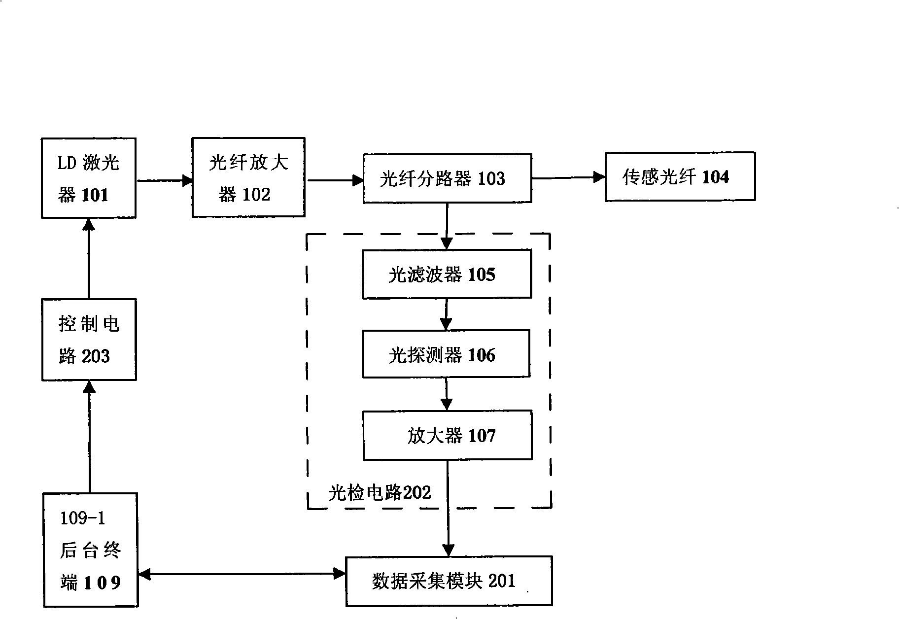
[0030] A complete wide-area all-fiber disturbance sensing and positioning network system is attached figure 1 shown.

[0031] a. Logically controlled by the background terminal 109 to generate a pulse drive, and then the LD laser 101 generates a pump light pulse, which is boosted by the optical fiber amplifier (EDFA) 102 and then coupled by the optical fiber splitter (3dB optical coupler) 103 Into the sensing fiber 104, backscattered light will be generated in the sensing fiber 104, and the returned backscattered light is then coupled to the optical filter 105 by the fiber splitter 103 for filtering and separation, thereby obtaining backward Rayleigh scattering Since then, the acquisition of the signal has been completed.

[0032]b. The backward Rayleigh scattered light separated from the optical filter 105 enters the photodetector (PD) 106 for photoelectric conversion, and then is amplified by the previous stage to complete the photoelectric detection of the signal.

[0033...


PUM


Abstract

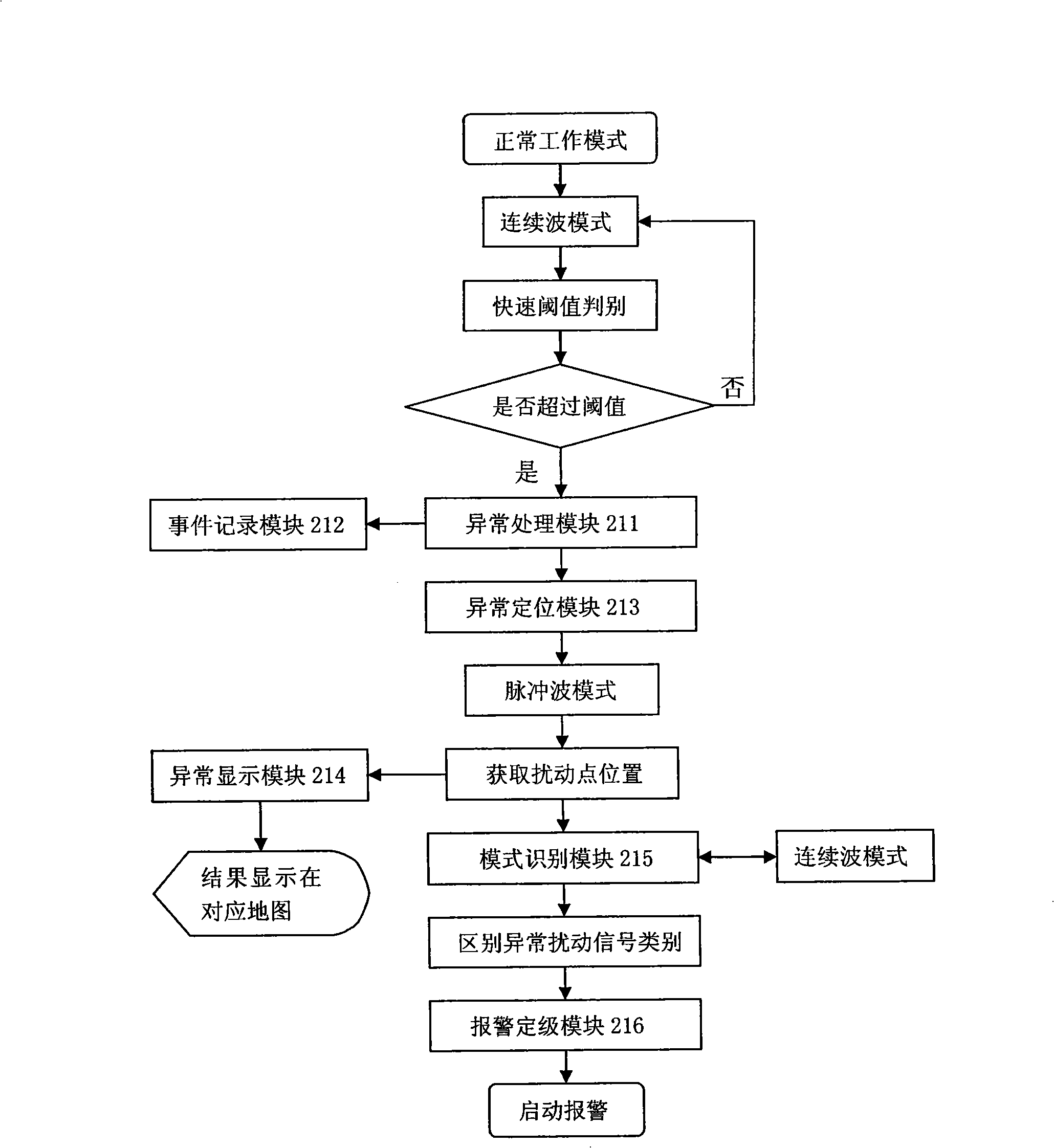
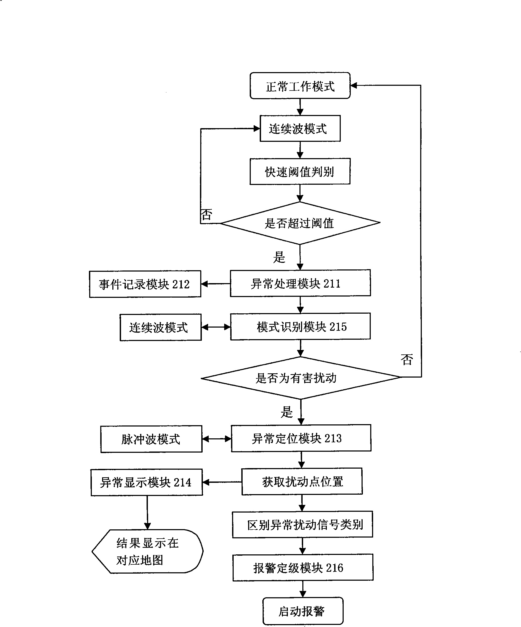
A front-rear discriminating method of wide domain complete optical fiber disturbance signal is principally used in conduit monitoring, such as conduit safety monitoring of various conveying danger or high value chemical industry article, which specially includes: the background terminal controls the operation of the entire wide domain complete optical fiber disturbance testing system, which is divided into two operation modes, a front discriminating rule and a rear discriminating rule; when the system is at the operating system, the systems produces a control command by a control circuit, and the control circuit controls the selection of the detection mode, which allows the system to work at the continuous wave mode or at a pulse mode; in the continuous operating mode, the system detects whether the disturbance sensing signal appears; while in the pulse operating state, the system sends out and detects a location signal, and locates the disturbance sites; in the selected operating mode, the system completes the photo-electric detection relative to the operating mode, the photoelectric signals are amplified and conditioned in the photo-electric detection circuit, and then are captured in a data acquisition module, the captured signals form a disturbance sensing signal processing result after processing.

Description

technical field [0001] The invention is mainly used for pipeline monitoring of various types of dangerous or high-value chemical product pipeline safety monitoring and monitoring. It is a disturbance positioning signal processing technology for a wide-area all-fiber disturbance sensing and positioning system for perimeter security defense, which belongs to the optical fiber Sensing technology field. Background technique [0002] Optical fiber sensing technology is a brand-new sensing technology developed rapidly in the 1970s with the development of optical fiber and optical fiber communication technology. In a nutshell, a fiber optic sensor is a device that uses an optical fiber to modulate the light wave parameters transmitted in the fiber to be measured, and demodulates and detects the modulated light wave signal to obtain the value to be measured. [0003] The principle of the wide-area all-fiber positioning network system is based on the Rayleigh backscattering effect i...

Claims


Application Information

Patent Timeline
IPC IPC(8): H04B10/08G02B6/42G01D5/353G01H9/00G01L1/24
Inventor 赵兴群孙小菡陈卿韦朴丁东韦恩润冯宏伟
Owner SOUTHEAST UNIV
Learn More