Symbol timing synchronizing apparatus for complete digital receiver

A symbol timing synchronization and all-digital receiver technology, which is applied in the direction of synchronization devices, digital transmission systems, electrical components, etc., can solve the problem of inability to ensure the best value, the degradation of receiver performance, and the selection of sample points that cannot be oversampled, etc. problem, achieve the effect of streamlining multiplier redundancy, reducing the number of multipliers, and removing single estimation errors

CN101299657AInactive Publication Date: 2008-11-05SHANGHAI JIAO TONG UNIV
0 Cites 40 Cited by

Patent Information

Authority / Receiving Office
CN · China
Current Assignee / Owner
Publication Date
2008-11-05
Estimated Expiration
Not applicable · inactive patent

Smart Images

  • Figure 1
    Figure 1
  • Figure 2
    Figure 2
  • Figure 3
    Figure 3
Patent Text Reader

Abstract

A complete digital receiver symbol timing synchronizing apparatus of the digital communication technique domain, includes an interpolator, a sampling clock frequency error estimation module, a loop filter, an interpolation controller, a sampling clock phase error calculation module and a sampling phase selection controller, wherein, the sample value of the system over-sampling is taken as the input of the interpolator; the sample value result after the regulation of the interpolator output is taken as the input of the sampling clock frequency error estimation module, for finding the correct sampling point position; the sampling phase selection controller sends out commands to control a lower sampling device, thereby making the lower sampling device complete sampling in the optimum time; the output result of the lower sampling device is taken as the input of the sampling clock frequency error estimation module, for calculating the sampling clock frequency bias; the interpolation controller controls the work process of the interpolator according to the sampling clock frequency bias fed in from the loop filter, for implementing the exactness correction to the sampling values. The loop circuit structure of the invention is quite simple, and is realized by hardware in the digital domain.
Need to check novelty before this filing date? Find Prior Art

Description

technical field

[0001] The invention relates to a synchronization device in the technical field of digital communication, in particular to a symbol timing synchronization device for an all-digital receiver. Background technique

[0002] With the development of digital signal processing technology and the reduction of device cost, the transceiver of digital communication system is developing towards the direction of full digitalization and softwareization (software radio architecture). Symbol timing is the key technology of all-digital receiver, and it is the basis of correct sampling judgment. The quality of system timing will directly affect its performance. This is also the most challenging part of an all-digital receiver. Due to the channel transmission delay and the clock offset caused by the unstable operation of the oscillator, the sampling clock frequencies at the two ends of the transceiver will not be exactly the same, so there is a small deviation between the samp...

Examples

Embodiment Construction

[0033] The embodiments of the present invention are described in detail below in conjunction with the accompanying drawings: this embodiment is implemented on the premise of the technical solution of the present invention, and detailed implementation methods and specific operating procedures are provided, but the protection scope of the present invention is not limited to the following the described embodiment.

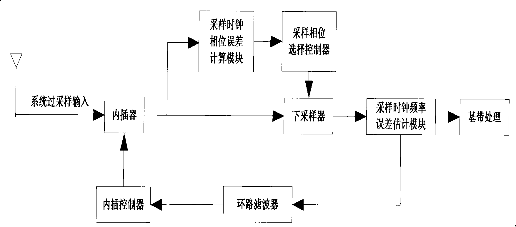
[0034] figure 1A general structural block diagram of the device for synchronizing the symbol timing of the all-digital receiver according to the preferred embodiment of the present invention is shown.

[0035] refer to figure 1 , the timing synchronization device includes: an interpolator 100, a sampling clock frequency error estimation module 200, a loop filter 300, an interpolation controller 400, a downsampler 500, a sampling clock phase error calculation module 600, and a sampling phase selection controller 700. The connection relationship between these compone...