Bionic robot fish having up-down movement module and tail module
A technology for robotic fish and fish body, applied in the field of bionic robotic fish, can solve the problems of inconvenient adjustment of tail fin motion parameters, poor motion stability, low speed of ascending and diving, etc., and achieves inconspicuous fish body swing, easy adjustment, and motion stability. Good results
- Summary
- Abstract
- Description
- Claims
- Application Information
AI Technical Summary
Problems solved by technology
Method used
Image
Examples
specific Embodiment approach 1
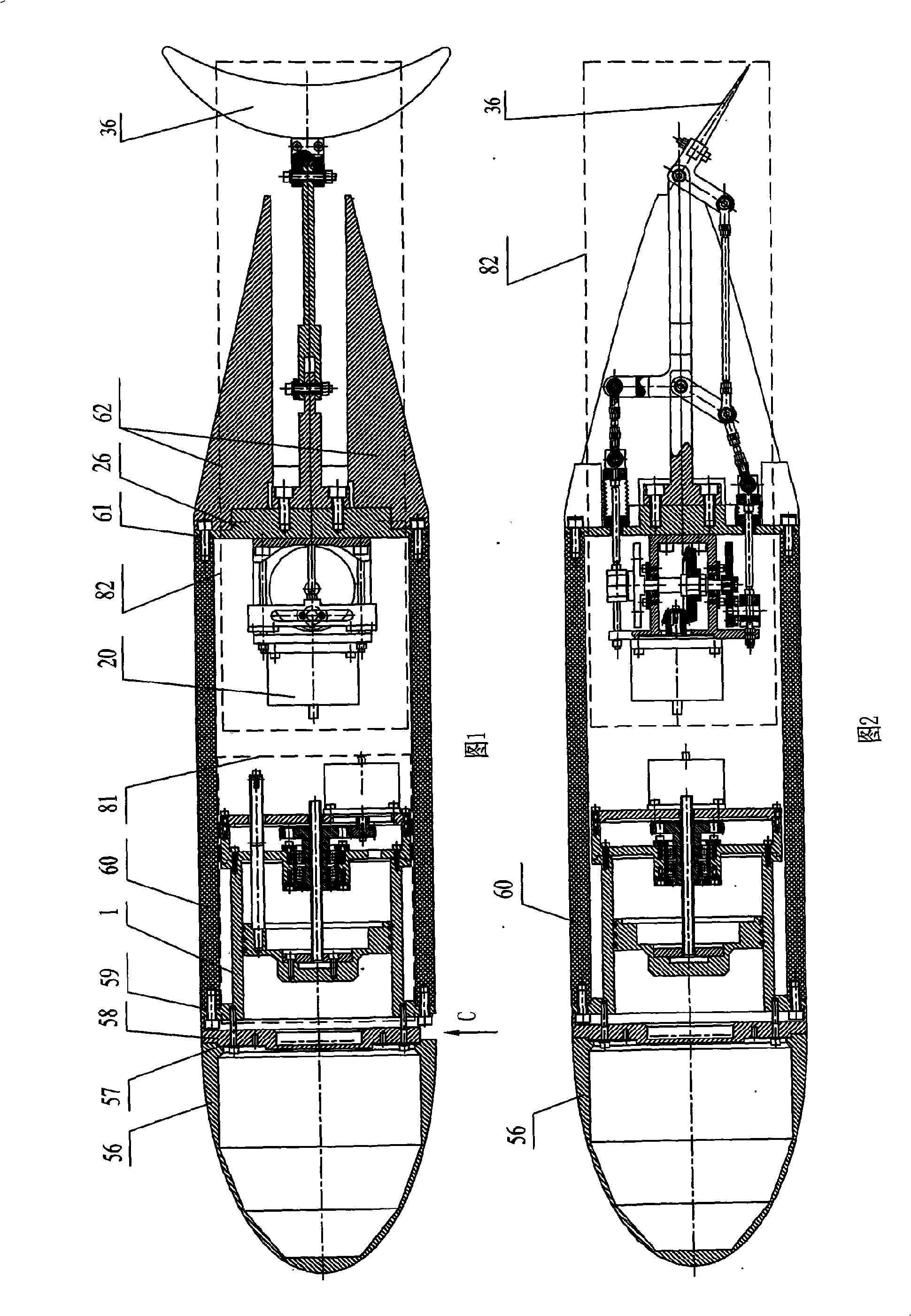
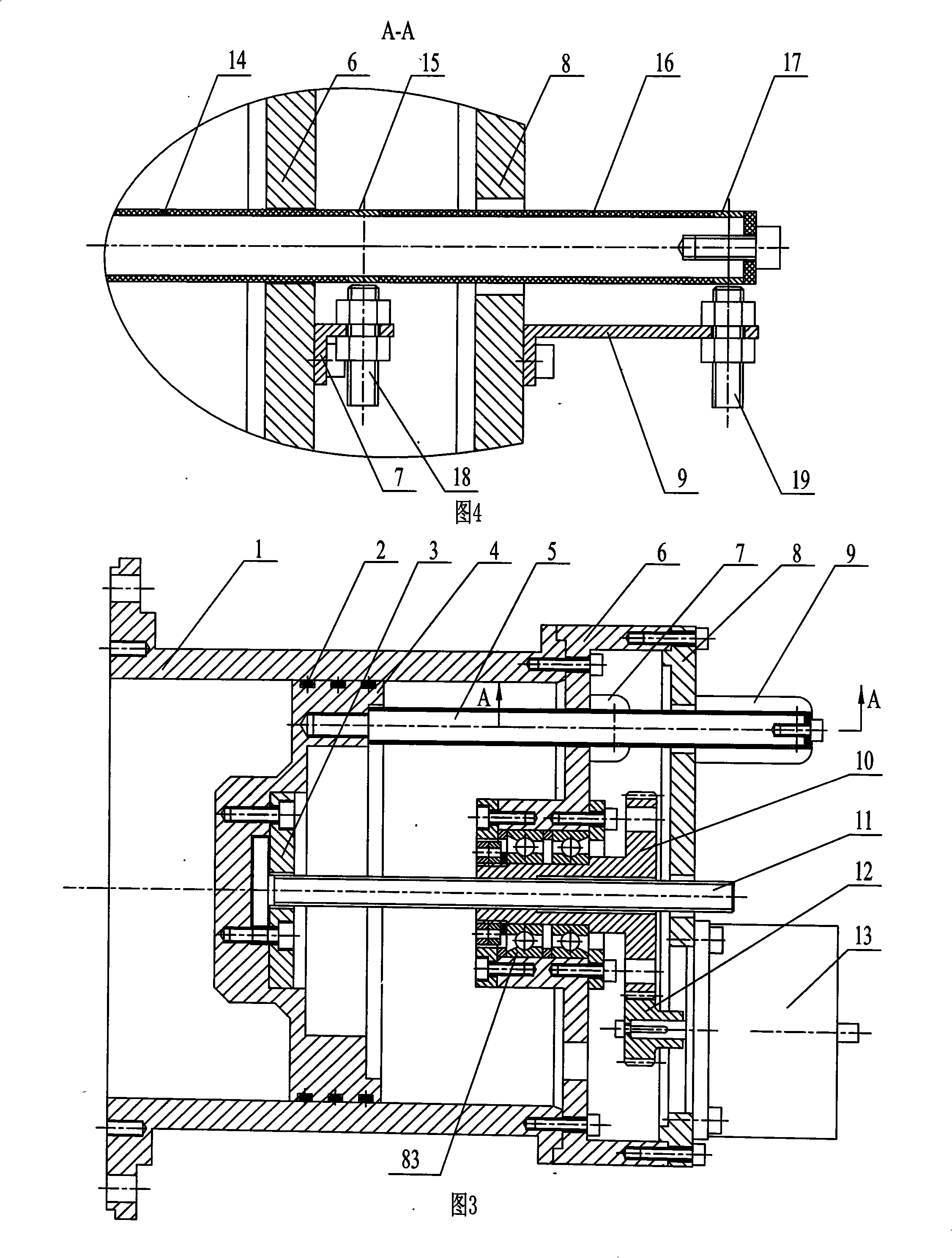
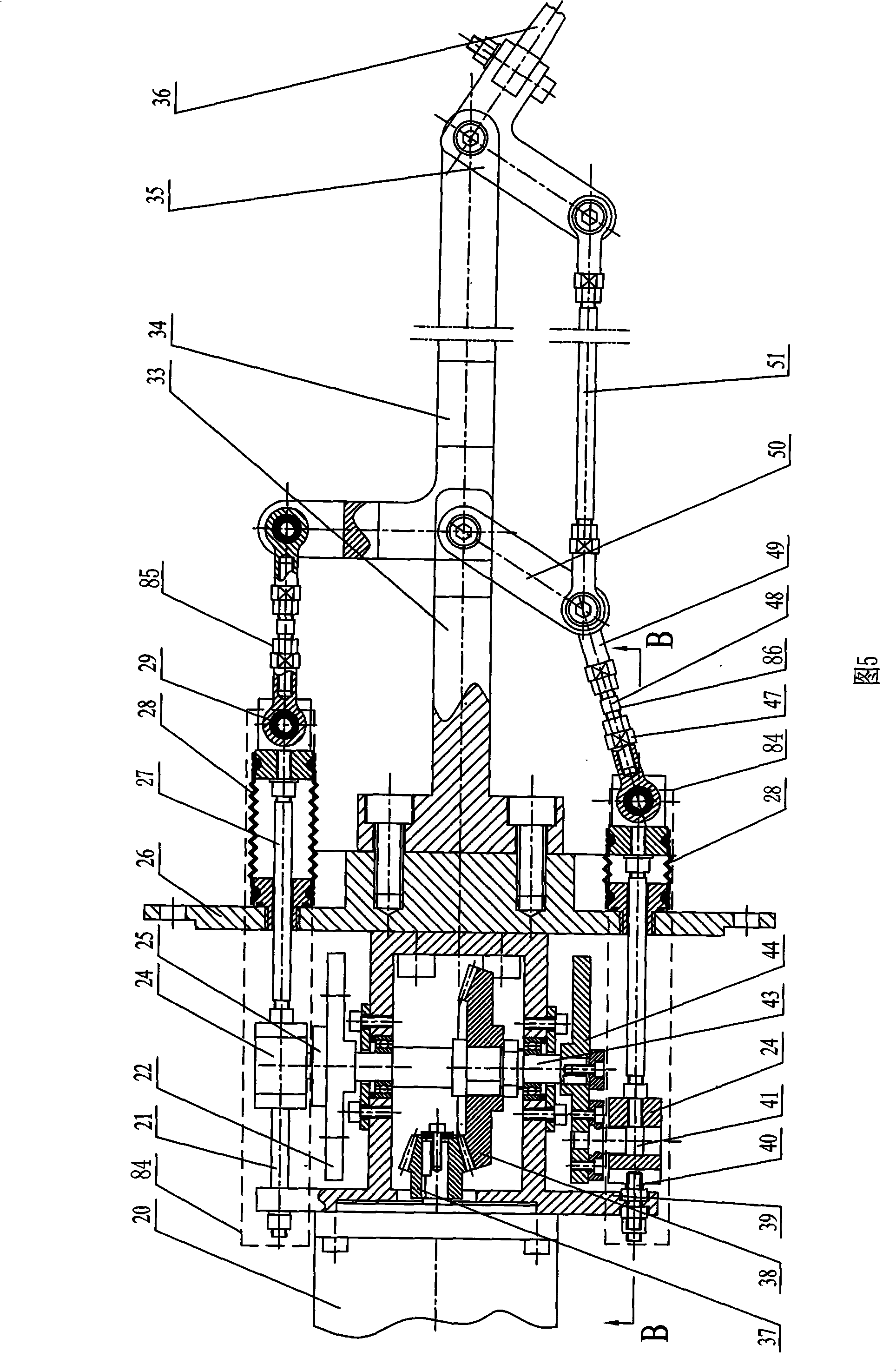
[0008] Specific Embodiment 1: As shown in Figures 1 to 6, the bionic robotic fish having a diving module and a tail module described in this embodiment includes a semi-elliptical fish head 56, a fish body circular tube 60, Conical tail body 62, support 58, the bionic robotic fish also includes a diving module 81 and a tail module 82; the diving module 81 includes a DC torque motor 13, a spur gear 12, a spur gear 10, Lead screw 11, cylinder 1, piston 4, lead screw end cover 3, cylinder end cover 6, motor support 8, bearing assembly 83; the tail module 82 includes a tail module DC torque motor 20, a straight-toothed conical small Gear 37, spur gear 38, box body 39, central shaft 43, first disc 22, second disc 44, first eccentric shaft 25, second eccentric shaft 41, two sets of sliding mechanism assemblies 84, The first connecting rod assembly 85, the second connecting rod assembly 86, the end cover 26, the tail support 33, the L-shaped tail handle 34, the swing handle 50, the L-...
specific Embodiment approach 2
[0009]Specific embodiment two: As shown in Figures 1 to 6, the two sets of sliding mechanism assemblies 84 in this embodiment are composed of sliders 24, two linear guide rails 21, two linear bearings 23, pull rods 27, and telescopic rubber tubes. 28, the two linear guide rails 21 horizontally pass through the through holes 24-1 on both ends of the slider 24, and the two linear bearings 23 are respectively installed between the two linear guide rails 21 and the slider 24, and The two linear bearings 23 are fixedly connected to the slider 24 respectively, and the two ends of the two linear guide rails 21 are fixedly connected to the box body 39 and the end cover 26 respectively, and the slider 24 is provided with a long hole 24-2 along the length direction. A slide block in the two slide blocks 24 is installed on the eccentric position of the first disc 22 by the first eccentric shaft 25 installed in its elongated hole 24-2, and the other slide block in the two slide blocks 24 ...
specific Embodiment approach 3
[0010] Embodiment 3: As shown in FIG. 5 , the first connecting rod assembly 85 and the second connecting rod assembly 86 in this embodiment are both length-adjustable connecting rods. Both the first connecting rod assembly 85 and the second connecting rod assembly 86 are composed of a front joint 47, an intermediate connecting rod 48, and a rear joint 49. The two ends of the intermediate connecting rod 48 are respectively processed with left-handed threads and right-handed threads. The front joint 47 and the rear joint 49 are screwed through the middle connecting rod 48 . The length of the first connecting rod assembly 85 and the second connecting rod assembly 86 can be changed by rotating the middle connecting rod 48. The correction of the initial position of the tail handle can be realized by adjusting the length of the first connecting rod assembly 85. By adjusting the second The length of the connecting rod assembly 86 can realize the adjustment of the water striking angle...
PUM
 Abstract
Description
Claims
Application Information
 - R&D
- Intellectual Property
- Life Sciences
- Materials
- Tech Scout
- Unparalleled Data Quality
- Higher Quality Content
- 60% Fewer Hallucinations
Browse by: Latest US Patents, China's latest patents, Technical Efficacy Thesaurus, Application Domain, Technology Topic, Popular Technical Reports.
© 2025 PatSnap. All rights reserved.Legal|Privacy policy|Modern Slavery Act Transparency Statement|Sitemap|About US| Contact US: help@patsnap.com


